Process engineering design
Solutions for quick and easy P&ID creation
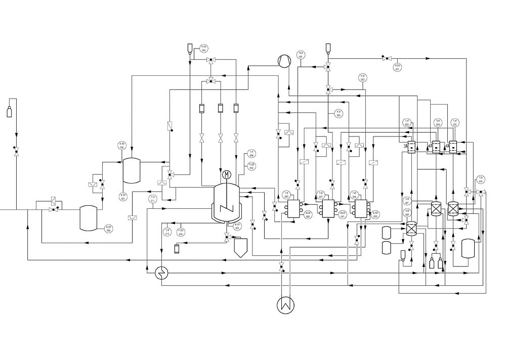
The piping and instrumentation diagram (P&ID) is a standard document used in process engineering design. Due to its schematic representation, internationally recognised symbols, and detailed parts list, the P&ID is very clear and easy to understand. This makes it one of the most important means of communication for everyone involved in the design process. Software for generating P&IDs is therefore one of the fundamental prerequisites for barrier-free design in plant construction.


Intelligent Piping & Instrumentation Diagrams
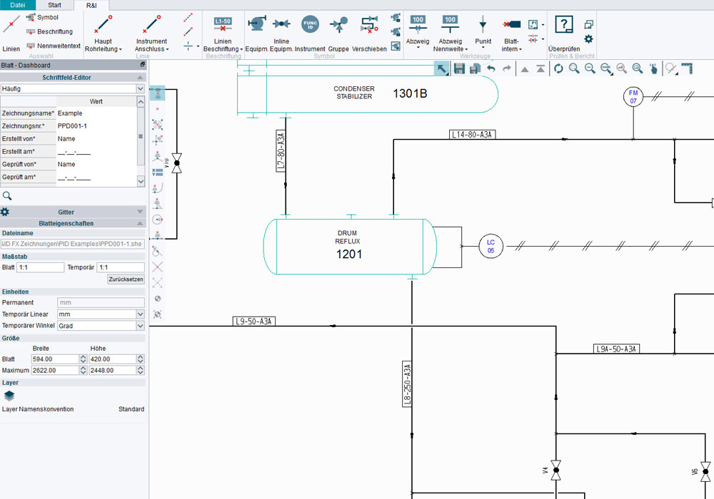
With its intelligent P&ID solutions, CAD Schroer offers comprehensive software packages for process engineering design. The software is equipped with industry-standard symbol libraries, and also offers the capability of enriching the resulting P&IDs with additional information. This information can be reused later on in the design process, for example, in the form of parts lists to facilitate cost estimation, and to ensure consistency during subsequent 3D design. A built-in P&ID checker also ensures maximum quality by reporting design and user errors early on in the P&ID creation process.
Full cost control thanks to intelligent P&IDs
The information stored in each P&ID can be accessed at any time and can also be exported in the form of customisable parts lists. CAD Schroer’s P&ID solutions offer a high degree of flexibility and support multiple file formats so that the parts lists can be reused seamlessly in other systems, thereby helping you to achieve full cost control over the entire project.

