What's New in Version 7.2
General improvements
Optimisation for high-resolution monitors
The variety of monitors and their resolutions has increased significantly in recent years. In version 7.2 of M4 PLANT & M4 DRAFTING, support for high-resolution monitors (e.g. 4k monitors) has been optimised. To match this, the user can now use even larger icons in the software. For display in large screen resolutions up to 4K (3840 x 2160), two new icon sets have been introduced (xlarge and xxlarge). The optimisation for high-resolution monitors also includes the improvement of the display in different scales, which can be made in the Windows operating system settings for the screen.
Simplified configuration of the licence server
Version 7.2 of the M4 product range comes with a new administration tool for the licence server. It displays the installation status of the licence server software and the status of the licence service. Different options are available, that greatly simplify the installation and administration of the licence server. With the help of the program a new licence file can be imported, the licence service can be started and stopped or existing licence server installations can be updated. The software supports the administrator at every step and also automatically creates backups.
Automatic activation of single-user licences
From version 7.2 of M4 PLANT and M4 DRAFTING, single-user licences (from local licence files) are automatically recognised and activated; they no longer have to be activated separately.
New functions, updates and changes
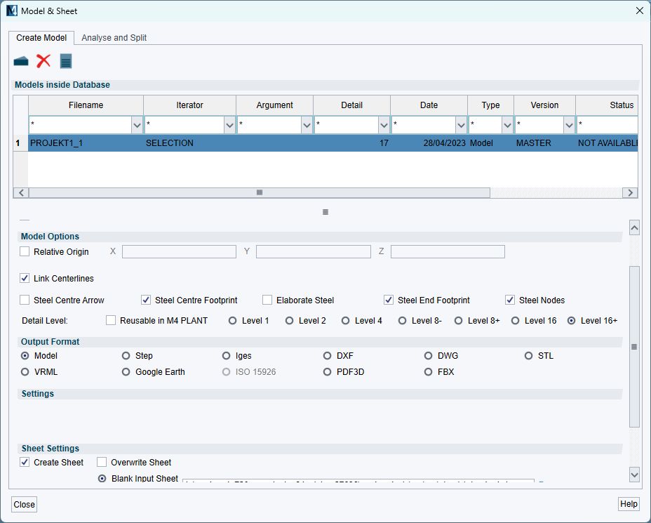
Create models and drawing derivations in the background
Exporting extensive 3D data or processing 3D data into 2D drawings can take some time in certain circumstances. From version 7.2 of M4 PLANT, the processes for conversion or generation of drawings are started as a background process. This means that the user interface is no longer blocked and the M4 PLANT user can continue working on the design during the export. In addition, the performance of the actual conversion has been improved.
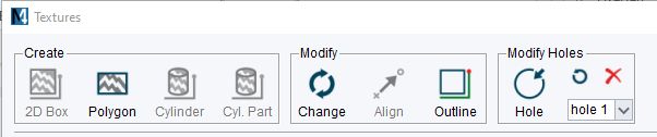
Improved editing of textures
The creation and editing of textures has been improved in M4 PLANT version 7.2. For example, tools for adjusting polygon textures have been added, making it very easy to adjust and rework the outer contours or holes.
Multiple selection for systems, subsystems and disciplines
Due to the improved selection filters, several systems, subsystems or disciplines can now be selected at the same time. This new multiple selection option eliminates the need for additional work steps, which saves time.
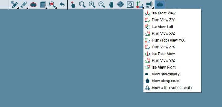
New Options for the selection of the view
The Options for selecting standard views have been optimised and extended.
Factory Layout
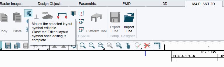
Open and Edit symbols
2D symbols for creating a layout with the Factory Layout module in M4 PLANT could not be edited until now. With version 7.2, these can now be opened for editing and then closed again. This provides the user with additional editing options for the layout process.
Steel Construction
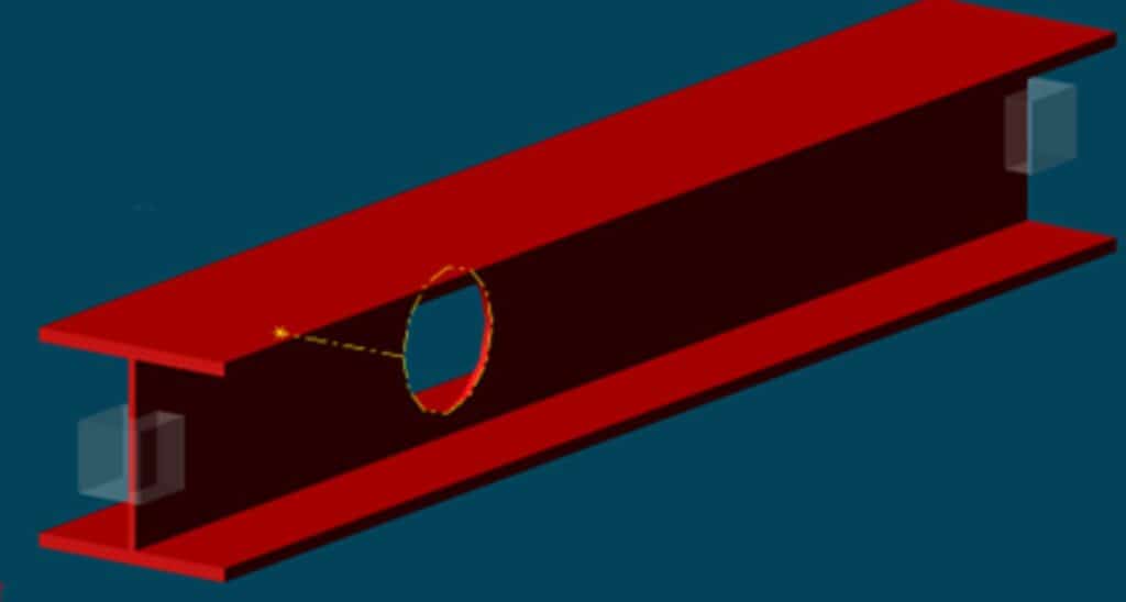
New function for creating holes in steel beams
In M4 PLANT version 7.2, the steel construction module has been extended with the function for creating holes in steel beams. This function is very similar to the well known function for creating holes in steel plates. It also uses the Route tool to define the profile that will be turned into a hole.
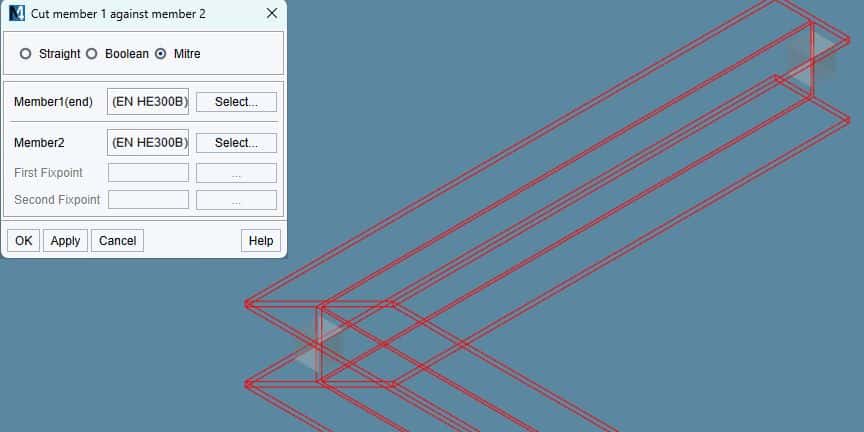
New function for creating mitre cuts
As of version 7.2, the dialogue for creating cuts between steel beams and the option for creating mitre cuts have been extended. This means that two steel beams can now also be connected with a mitre cut.
P&ID
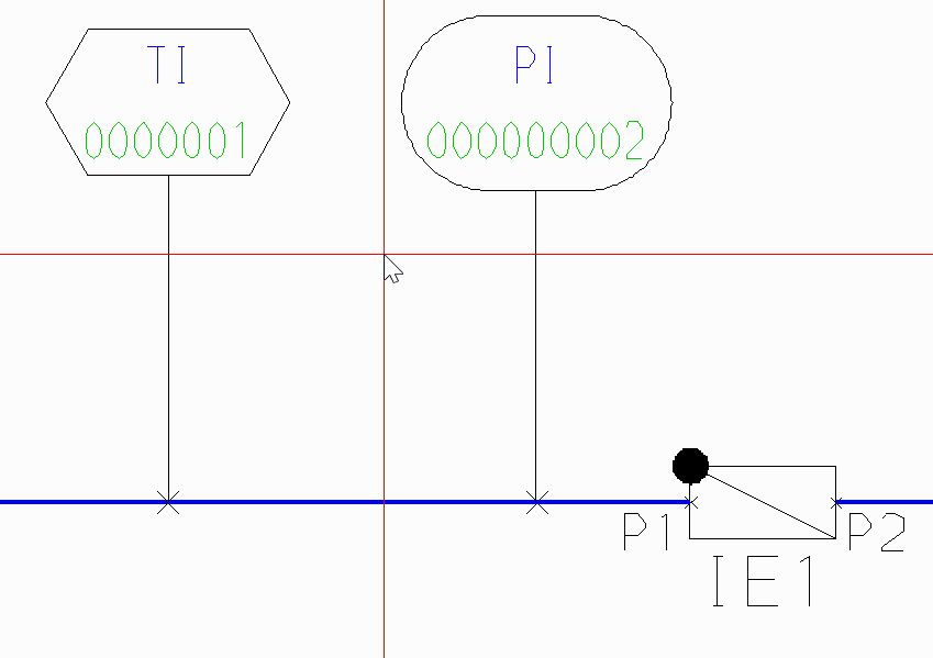
Dynamic Instrumentation Symbols
P&ID instrumentation symbols adapt to the texts they contain as of version 7.2. If the numbers or texts are short, they remain round. If the texts become longer, the symbols are stretched according to the text length.
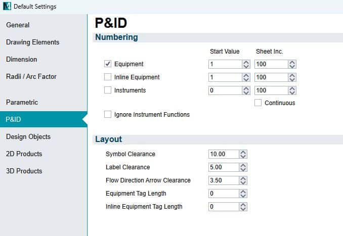
New area for P&ID options
In version 7.2, the settings for the P&ID module have been given a new area in the preferences. The settings apply to all P&ID schemes created and modified in M4 DRAFTING. They can be changed centrally at this point for a specific customer project.
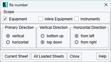
Improved automatic renumbering of symbols
Based on customer feedback, the renumbering tool has been optimised. The settings for the start value and the increment were moved to the default settings.
3D
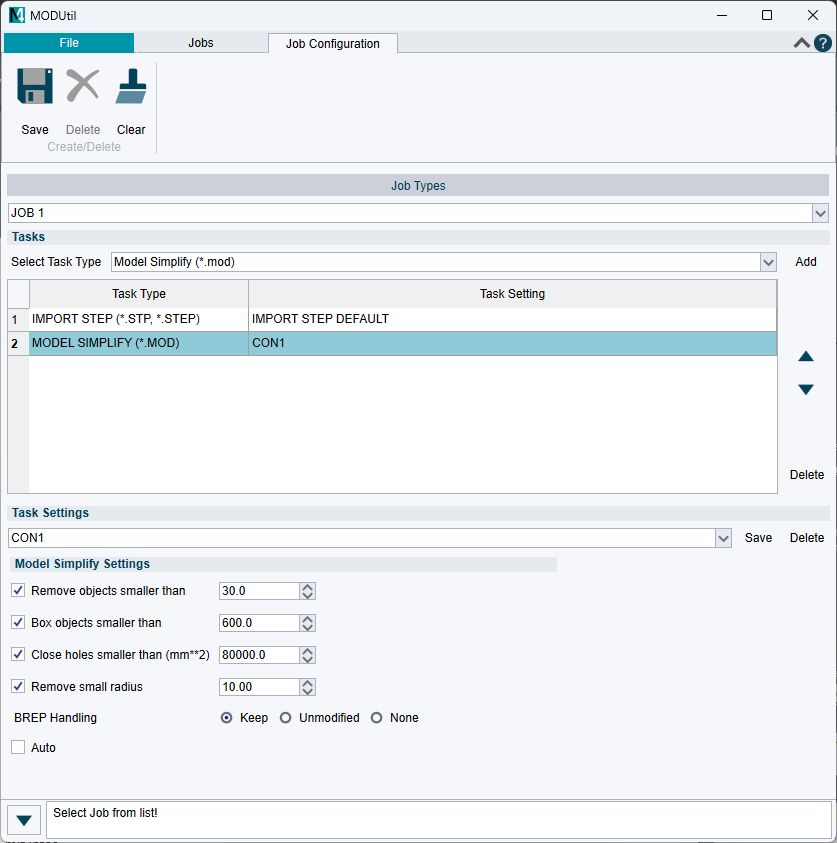
A new stand-alone tool for model conversion
From version 7.2, M4 PLANT and M4 DRAFTING include a new stand-alone tool for the automated conversion of files in 3D formats. MODUtil is started independently of M4 PLANT and M4 DRAFTING. It allows both single conversions, e.g. exporting MOD files into STP format, and chain conversions, e.g. importing STP files with downstream simplification of the model.
The conversion programmes that MODUtil uses are command line programs. They are continuously being developed.
The options for each individual conversion program are compiled in the graphical user interface. They can be selected very conveniently from there and saved under a name (task configuration).
The composition of individual tasks can also be saved (job configuration).
Task configurations and job configurations can be compiled by the administrator or by experienced users and then made available to all users.
You start a job by applying a job configuration to one file or to all files in a directory. You can conveniently have time-intensive conversions carried out overnight.
Transfer of the assembly structure from STEP files
As of version 7.2, STEP files can be imported including the assembly structure they contain. The structure is retained both after the import and after the simplification of a model. The structure can then be used in 3D Design process for further tasks, such as processing in the M4 PLANT Component Designer, or subsequently being used when exporting to other formats. It can also be viewed in the 3D viewer M4 REVIEW. In the same way, it can be transferred to the VR-capable FBX format. In addition, the BREP (representation of the models as Boundary Representation) are also transferred to the MOD file during the STEP import.
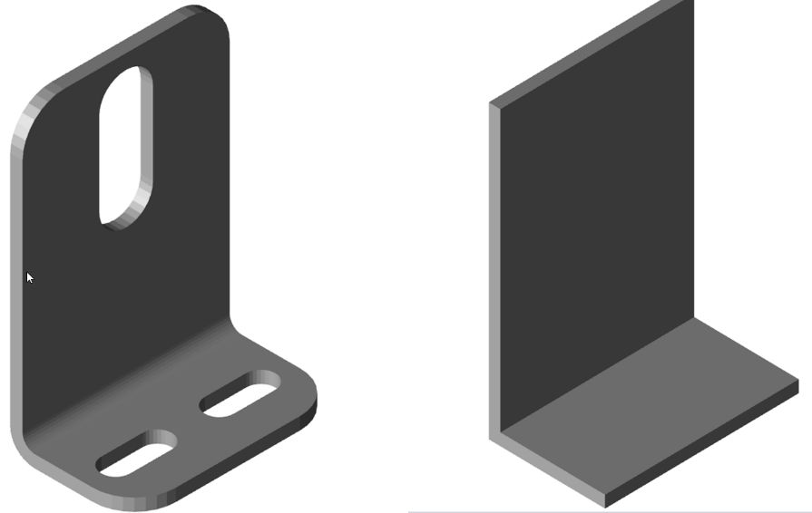
Better simplification of models
Large 3D models should be simplified before they are loaded into M4 PLANT. The data reduction achieved by model simplification should be such that the models can be processed in M4 PLANT smoothly and without loss of performance. With version 7.2, further options for simplifying models have been added to the MODSIMPLIFY module. Users can now remove radii from models by specifying a maximum radius when simplifying a model. When simplifying, smaller radii are then detected and converted to a simple edge. Likewise, the closing of holes in models has been optimised.
2D
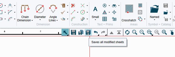
Save All function in the graphical toolbar
For quick access to the “Save All” function, from version 7.2 this function is now also offered in the graphic toolbar. This allows the changes in all drawings loaded in M4 DRAFTING to be saved at the touch of a button.
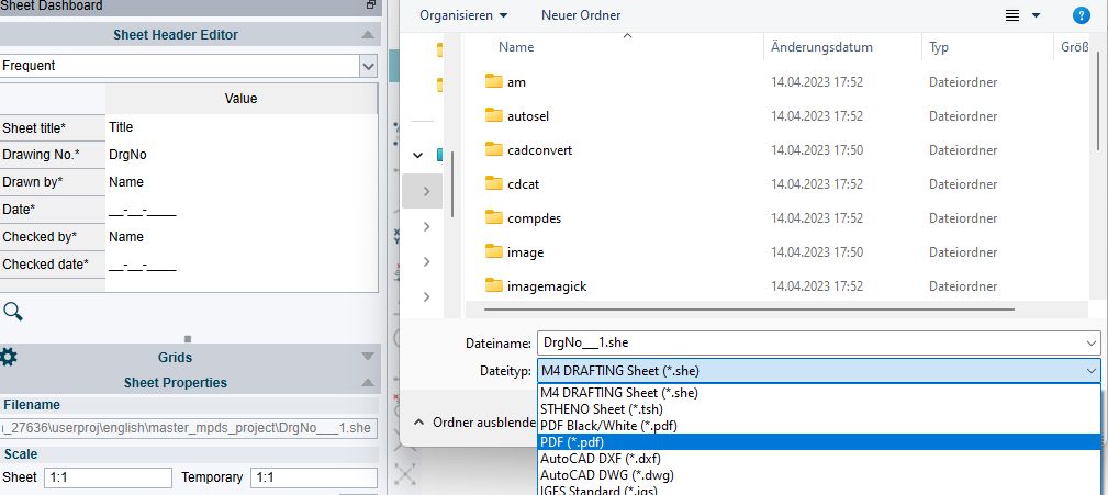
Save drawings as PDF
Saving the drawings as a PDF becomes easier. In the save dialog, the user can choose whether to save the current drawing as a colour or black and white PDF.
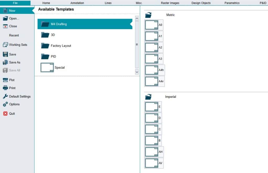
Drawing templates
In version 7.2 the handling of drawing templates in M4 DRAFTING has been optimised once again. All available drawing templates are now displayed in the ribbon menu item: New. There are M4 DRAFTING standard templates for metric and imperial drawings as well as customer-specific (own) templates. The grouping into M4 DRAFTING (2D), 3D, Factory Layout (FL) and R&I (PID) is new.
Invert zoom direction
As of version 7.2, the direction of the zoom function on the mouse wheel can be reversed in M4 DRAFTING. This means that users who are used to a different orientation of the mouse wheel zoom can now set it according to their personal needs.
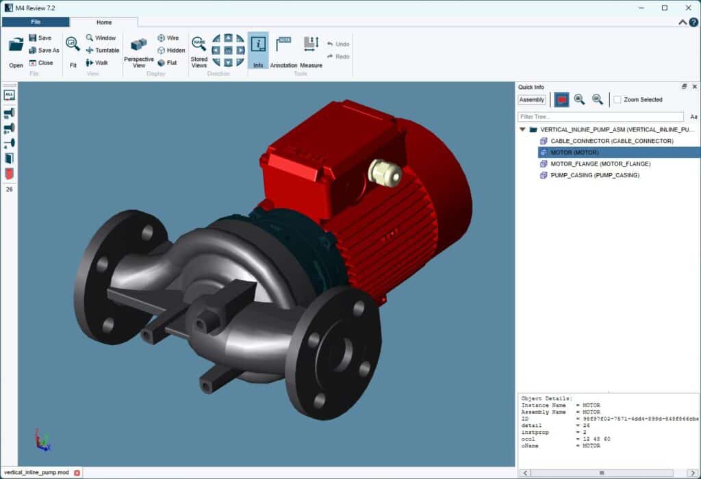
M4 REVIEW
With the new version of M4 REVIEW, structures of imported STEP files can now be viewed. This function is not supported in the free version.
Improvements to the software requested by customers
In addition to the many innovations, the new version of M4 PLANT & DRAFTING 7.2 also includes solutions for over 300 improvement requests reported by customers.
Building design and layout
Optimized placement of doors and windows
In M4 version 7.1, the placement of doors and windows has been further optimized. To this end the individual catalogues have been improved and the dialog for placing the individual components has been re-created. Previews for doors and windows as well as extended measuring tools are now available. These improvements simplify the selection of suitable doors and windows for the user in order to be able to place them more quickly in the design.
New: 3D preview for steel columns
In M4 version 7.1, a 3D preview window has been added to the selection dialog for columns. This is particularly practical because the user can view the currently selected component exactly in 3D and then place it in their design.
3D
Improved section definition for 3D models
As of version 7.1, the M4 3D module contains a new tool for defining sections. With the help of a line, sections can be easily created through the model; these are then displayed directly in a different view. The new tool simplifies the section definition and makes it far easier for the user to show sectional views.
P&ID
Optimization of the P&ID renumbering tool
Renumbering of complete drawings is a clever way to keep the numbering of copied elements in a drawing consistent with the ever changing customer requirements. This function allows duplicate elements to be automatically renumbered so that components with the same ID are not created. In version 7.1, this function has been extended to loop IDs of instruments; meaning the user can now also correctly rename the instruments used.
New: Instrumentation with alarm attributes
With version 7.1, the alarm attributes for instrumentation symbols are displayed di-rectly in the dashboard of the P&ID module. These are then automatically displayed as texts next to the symbol. This feature makes it easier for the user to place alarm attributes, saving time in terms of configuration and administration; compared to add-ing unconnected texts manually to the diagram.
Better configuration of P&ID reports and BOMs
With the current M4 version 7.1, P&ID reports and parts lists configuration has been enhanced. The user can now configure the pipeline lists in more different formats. With this new configuration, for example, the devices connected to the pipeline can be output in a line list. Column widths for individual attributes can now be specified as a percentage of the available space allowing the user to optimize the layout of their report as needed.
Better search in the P&ID symbol browser
New features such as improved filters for searching in the P&ID symbol browser make it even easier to find the individual components in the symbol browser in M4 version 7.1. To do this, the user only needs to enter criteria to search through the catalogs, groups or individual symbols and then have the results displayed live in the symbol browser.
Piping isometrics
New: Processing of PCF files
M4 PLANT version 7.1 gets a new tool to create piping isometrics from a PCF file within the 2D environment. With the new tool, native M4 ISO files in ISOX format or the piping isometrics exported from third party systems in PCF format can now be opened and conveniently converted into a piping isometric drawing. The user can choose from several options and adapt the isometric drawing to their requirements. They select the desired template and the correct style for the isometric. This new function makes pipeline documentation with M4 PLANT even easier, as pipeline isometrics can now also be created from third-party systems.
New border styles for notes
As of version 7.1, user notes automatically placed in the pipeline isometric geometry can be provided with different borders. The user can freely select the border style before the automatic generation of the isometric.
Better support for the imperial measurement system
As of M4 PLANT version 7.1, the pipe isometric module included in the software also supports the display of fractional values for inches (e.g. 20 ¼”) and for feet& inches (e.g. 4′ 20 ¼”) units of measurement. The software will automatically apply the appropriate units of measurement to all documents created. These new options allow companies to provide the required piping isometrics with the appropriate units of measurement for the project and thus to operate internationally.
Manual division of pipelines into several isometrics
As of M4 PLANT Version 7.1, it is now possible to manually specify where in a pipeline string the geometry should be divided into several isometrics. This has the advantage that the readability of pipeline geometry is greatly increased when extremely complex pipelines can be manually divided into individual pipeline isometrics.
Table optimization
The tables that are generated together with the pipeline isometrics have been further improved in version 7.1. The user can adjust the individual widths of the cells and the texts to their own requirements. In detail the user can specify that the column width of the generated tables automatically adapts to the texts contained or that the texts are automatically wrapped to a specified column width. These settings significantly improve the readability and positioning of tables and ensure compliance with company and customer standards.
More options for dimension alignment
For an even better view in pipeline isometrics, from version 7.1 it is now possible to specify the alignment of the dimensions for skewed pipelines. These can now be aligned either to the horizontal or vertical isometric planes according to company standard.
Interfaces
New: Export of BIM planning data
As of version 6.3, M4 PLANT supported the import of IFC (Industry Foundation Classes) design data. IFC forms the open standard for BIM models (Building Information Modelling) is a primary, worldwide, open standard for data exchange in the construction industry. With version 7.1, the user can now export entire M4 PLANT projects in IFC format and participate more deeply in BIM projects.
Definition of background colors for 3D PDF export
As of version 7.1, the user can manually specify the background color when exporting a 3D PDF file from M4 PLANT; allowing them to create far more useful 3D PDF files.
Optimized interface for models to VR/AR
As of version 6.3, M4 PLANT included an export to FBX format. This allows 3D models in FBX format to be used directly in augmented or virtual reality (AR/VR) applications and viewers. With version 7.1, the FBX interface has been further improved with to transfer model structures, surface textures and model instancing. This means that the user can now use the M4 PLANT 3D design data far better in VR or AR applications.
Component catalogues
New: Preview window in the catalog selection
As of version 7.1, all the catalog selection dialogs in M4 PLANT include a 3D preview for the currently selected component. The preview window is now available for the piping, ducting, electrical and support catalogs and can be shown or hidden. The currently selected catalog component is displayed as a 3D model that the user can rotate , pan and zoom in the preview window; improving the selection of components for the designer.
Administration
Improved administration of pipeline specifications
With the new version 7.1, the administration of piping specifications in M4 PLANT has been significantly enhanced. Further options have been added to modify individual specifications. Users now also have the option of exporting individual specifications so that they can also use them in other projects.
M4 REVIEW
The new version 7.1 of the 3D viewer M4 REVIEW has been fundamentally enhanced. The selection and some viewing functions of the software have been optimized to further increase the performance of the software. In addition, the user can now also view M4 drawings in .SHE format, meaning that 2D and 3D views of the design can be reviewed in the same tool.
Support for Windows 11
With version 7.1, M4 PLANT supports Windows 11 from Microsoft. This allows you to use modern engineering software on the most current systems.
Customer requested improvements to the software
In addition to the many innovations and newly added products, the new version of M4 includes over 350 customer-oriented productivity improvements. These optimization requests are regularly submitted by CAD Schroer customers via the customer portal are prioritised and flow directly into software development.
i4 product family – AR/VR solutions from CAD Schroer
In recent years, CAD Schroer’s M4 engineering solutions have been joined by new i4 products that allow engineering data to be presented in Virtual or Augmented Reality environments. For example, with i4 MEETING, users are able to hold project meetings or product presentations directly in VR. With i4 VIRTUAL REVIEW, they receive a VR viewer with which they can dive directly into their 3D design. With i4 AUGMENTED REVIEW, the user can place their 3D modelled design directly on their coffee table or their hall floor for a closer look. i4 AUGMENTED CATALOG offers enhanced possibilities to enrich printed documents with an AR experience for the product portfolio; place your products in the real world direct from the electronic catalog.
New product names and packages
From version 7.0, all CAD Schroer products will be marketed under the M4 brand. The individual industry-specific product packages are given the appropriate product names, such as M4 DRAFTING for 2D design in mechanical engineering or M4 FACTORY for the 2D/3D layout in factory planning.
The complete range of all new packages and prices can be found under the respective product. An overview of our current product range can be seen in the following graphic.
New Features, Updates and Changes
2D Factory Layout: New Tools and Optimizations
Version 7.0 of the M4 Factory Layout Module has been significantly optimized and enhanced with additional functions. The improvements increase the design speed by a simpler user workflow.
Optimization and extension of the symbol catalog
M4 always offers the possibility to select 3D components from a catalog and to place them in a 2D layout as a symbol. The selection of the components has now been simplified by a symbol catalog. In addition, the standard supplied catalog compo-nents have been significantly extended.
Improved Catalog Selection of Components
In version 7.0, the selection dialog for catalog components has been re-created from the ground up, making it far easier to select components. The selection is enhanced by selection filters and a measurement function. In addition, individual variations for a attribute of the component can now be supplemented by descriptions. The catalog table columns are now customizable and can be modified to the requirements of the user.
2D/3D Groups for Components
The components scheduled in 2D can now be grouped in the structure tree. When loading the 2D layout in 3D, the groups are maintained and can be used here for further design purposes. In addition, these can be saved as a group component in the catalog for easy reuse. This optimization allows far better structuring of the design and much easier reuse of existing groups of components.
Structure tree for systems and subsystems in 2D
The M4 2D area now displays the 3D structure tree for the system and sub-system structure. Here you can view the individual scheduled components and select them for editing; the same mechanism in 2D and 3D.
2D Factory Layout Dashboard Optimized
The dashboard for editing the properties of factory layout components now includes an automatic check of systems and subsystems. This avoids incorrect or duplicate naming of systems and makes for better “right first time” design.
New: Production of steel platforms and staircases
M4 includes a new tool that allows you to easily create steel platforms with handrails and stairs in a 2D layout. Once a profile has been defined for a platform, it can be supplemented with the appropriate steel components such as steel girders, handrails, stairs and ladders. In addition, the steel plate can be provided with holes. The steel platform can also be easily modified at a later date. If, for example, the height of the platform is modified, all other components automatically change as well. Of course, the steel platforms defined in 2D are loaded as a detailed 3D model.
New Structure of Selection Tools
A new selection filter for factory layout elements in the 2D layout has now been add-ed to the selection tools. Additionally, a new selection tool for 2D Factory Layout el-ements has been added to the 3D area; select in 3D and it takes you to the 2D sheet and selects the 2d symbol in one click.
Optimization of the conveyor placement tools
The placement and processing of conveyor components has been further optimized in version 7.0. The improved selection and placement mechanisms have made fast planning very important. The user now has the option of having a conveyor section between two components created completely automatically in 2D. The system then automatically compensates for the height differences and displays the heights at the individual components. With these tools, the length or height of the placed conveyor elements can be changed. Individual elements can also be individually edited after placement by conveniently adjusting the individual parameters from a dialog. In addition, the Copy function has been extended so that the copied conveyor section can now also be mirrored in either axis.
Easier modification of 3D models for the 2D layout
Starting with version 7.0, M4 offers the possibility to edit a 3D model directly within the 2D layout. With the help of a new tool, the user can easily stretch the 2D symbol and the 3D model is modified according to the symbol modifications and saved as a new model. This function offers the user the possibility to adapt 3D models to new requirements without having the design department create them again and again.
2D/3D Machine and Conveyor Catalogue
Renaming the Conveyor Technology Module
The Ribbon tab for placing conveyor components has now been renamed M+AEC (Mechanical, Architectural and Engineering Construction) to better reflect the current level of functionality.
Extension of the machine and conveyor technology catalogue
Version 7.0 of the catalogue now contains many other parametric standard compo-nents that facilitate the planning of complete plants or factories. These offer parametric standard components such as doors, security fences, containers or containers. The parameters of each component can be adapted to your own requirements when they are placed.
Save Component Groups as Catalog Components
Starting with version 7.0, complete groups of catalog components can be saved as a single component in the catalog. This function for creating group components accel-erates any future design and thus enables yet faster delivery of projects.
Piping design
Extension of the Pipeline Construction Catalogue
With version 7.0, the catalogue in the field of pipeline construction has once again been extended with new catalogue components. Users now have access to new catalogues from the PVC-C and hygienic clamping flange piping sectors. New catalogue components are supplied as packages and can be imported into the customers’ existing pipeline construction catalogue if required.
Configurable flange connection fixings
In the new version, flange fixings can be modified to new non default requirements after placement. The new “keep” option allows edits to be made to many connections at the same time, but only changing details which are not “kept”.
Improved generation of piping isometrics
In version 7.0, the module for the automatic generation of pipe isometrics has signifi-cant further improvements. The templates and styles already supplied in M4 ISO have been optimized to show that. The automatic placement of the individual sym-bols and labels has been improved, so that even very complex pipe situations can be optimally displayed and labelled in M4 ISO. In addition, the pipe isometric dialog has been extended with further options. These now allow the selection of a user coordinate system and the definition of optional split points. These allow pipeline isometrics to have more choice over orientation and split into individual drawings at the desired location.
More detailed parts lists
As of version 7.0, you can decide in each discipline whether the parts lists should only display total lengths or individual lengths. For each discipline, the user can decide whether, for example, he wants to see all pipe sections, steel members, cable trays or ventilation ducts with the corresponding lengths individually in the list or whether these should be output as a total length.
Easier moving of individual projects
With version 7.0 M4 offers an even easier way to customize project directories or to organize them. With the new tool, all resources used in the project can be viewed with their file paths and the individual paths can be adjusted. This makes it far easier to adapt projects to new requirements and safely modify them in the future.
P&ID
User-dependent Standard Attributes for Line Labels
The P&ID tool for pipe labelling now allows the definition of user-dependent standard attribute values. The user can define standard values for the currently used attributes within a session. This allows the user to temporarily change the standard attribute values within a project and thus further accelerate the pace of design.
Optimization of the renumbering tool
M4 has supported the renumbering of complete drawings since the version 6.3. This function makes it possible to renumber many copied elements in a drawing so that no components with the same name are used. In version 7.0 this function has been extended to instrumentation, so that the used instruments are now renamed correctly.
Extension of the sheet connector dialog
M4 allows the connection of several drawing sheets into one design project. The lines are connected logically between the individual drawings by sheet connectors. With version 7.0, the Sheet Connector dialog now shows the user which connections are not yet paired in a selection dialog; so the “not yet connected” lines can be easily selected and continued on the current sheet.
Custom Subtypes for Components
M4 offers a default structuring of all components, by types and subtypes; whereby a simpler structuring and parts list generation is made possible. As of version 7.0, the subtypes of the components can be freely edited and individually selected. Direct entry of a new subtype is also possible.
Symbol Favourites
Starting with version 7.0, M4 now offers the option of saving individual P&ID symbols into a favourite’s area of the symbol tab. This is done conveniently via the context menu, where the currently selected symbol is added to the favourites. Favourites created in this way are used to generate diagrams even faster, thus saving design time.
Use of connection points for equipment placement
M4 now allows changing of the datum when placing a component. The individual connection points can be used as alternative datums. The selection can be made conveniently from the context menu.
Customizable Scaling of Different Symbol Types
In M4, the P&ID symbols are displayed as a preview in a clearly arranged dialog. The size of the symbols in the preview could be adjusted, but for all symbol types at the same time. Starting with version 7.0, M4 now offers the option of individually scaling the symbol sizes for each category. For example, symbols for equipment can now be displayed smaller than those for instrumentation.
Define nominal size for connection points
As of M4 Version 7.0, the connection points on the P&ID symbols can be provided with nominal diameters. These can then either be output in a report or used in 3D piping design to place the appropriate components; previous to Version 7.0 nominal diameters were only inherited from attached pipelines.
Move symbols by double-clicking them
As of version 7.0, symbols or line labels can be moved in M4 by simply double-clicking on the corresponding symbol. The current symbol is selected and the appro-priate move function is activated. This results in a significant reduction in user input and a decrease in design time; P&ID’s are amongst the most edited of drawings.
Automatic Creation of Symbol Legends
As of version 7.0, symbol legends can be generated in M4 for individual P&ID flowcharts or complete projects. These are generated either on the current sheet or on a new sheet. During generation, the user can decide exactly what the legend should contain. The user can decide between the current sheet, the entire project or an area in the catalog. The position and size of the legend can also be adjusted. This function eliminates the tedious manual creation of symbol legends, as these can now be generated project-specifically with just a few clicks.
Extension of the P&ID Administration
As of version 7.0, the P&ID administration includes additional options. For example, individual symbols, groups od symbols or complete symbol catalogs can be displayed or hidden from users. It is very common to use alternative symbol sets for different customers; this makes that very simple.
Better generation of parts lists
The generation of BOMs has been further improved in version 7.0. The dialog for generating BOMs has been simplified. Options for configuring the parts lists are now only visible when the user has logged in as admin. Parts lists, placed as table on a sheet, can be updated now rather than repalced. In addition, the BOM configurations are now stored in separate files, making it easier to exchange them between users.
M4 REVIEW
The new version 7.0 of the 3D viewer M4 REVIEW has been updated to the latest state of the art. The individual functions have also been optimized to increase the performance of the software.
Customer development requests
In addition to the many innovations and new products, the new version of M4 contains over 350 customer-oriented productivity improvements. These optimization suggestions are regularly submitted by CAD Schroer customers via the customer portal and are thus incorporated directly into the software development process.
New Products
Optimised: CSG Update Client
The CSG Update Client enables maintenance customers to update the software as easily as possible directly via the Internet. In the new version, the Update Client has been highly optimised and now additionally updates the software during the installation.
New: Help & Tutorial Dialogs
From version 6.3, MPDS4 and MEDUSA4 offers new dialogs giving the user a better overview of the available user manuals, video tutorials and release notes.
New: M4 VIRTUAL REVIEW
M4 VIRTUAL REVIEW is a new independent VR Viewer from CAD-Schroer and offers the possibility to have a virtual experience of the design data generated in MPDS4 or other CAD systems. The VR Viewer processes FBX data exported from MPDS4, so that a plant or factory, that is still in the planning phase, can experienced in virtual reality and presented far more effectively.
New Features, Updates and Changes
MPDS4 version 6.3 includes a large number of new functions. The expansion and optimisation of interfaces simplifies the exchange of data with customers and suppliers.
New: Import of BIM planning data
Version 6.3 of MPDS4 supports the import of IFC (Industry Foundation Classes) planning data. IFC is the open standard for BIM (Building Inofrmation Modelling) and represents a primary, worldwide, open standard for data exchange in the construction industry. With the new IFC interface, BIM data including its structure and context information can now be imported and placed in a design. This allows planning data to be transferred directly from an architect or steel designer and integrated directly into MPDS4.
New: FBX Export for Virtual Reality
Starting with version 6.3, MPDS4 now includes an export to FBX format in addition to all the other 3D interfaces. This makes it even easier to process the design data into visualization software packages. For example, they can be loaded directly in the new VR viewer M4 VIRTUAL REVIEW and viewed in immersively from the first-person perspective.
Recording Walkthroughs with MPDS4 ENGINEERING REVIEW
The MPDS4 Review visualization module has always offered users versatile visualisation options directly from the 3D design. Virtual tours, from the first-person perspective, have always been one of the module’s greatest strengths. Now the software also offers the possibility to save them in the form of high-quality videos. The user can choose the resolution as well as the format of the video recording. This means that the walkthroughs can now be used as videos for marketing purposes or for customer presentations.
Improved import of 3D models Simplification of Imported 3D Models
Starting with version 6.3, MPDS4 offers a new possibility for model import. The com-ponent designer in MPDS4 can now be used to import e.g. STEP models with the corresponding structure. When importing, the user then has the possibility to simplify a model, e.g. by deleting small parts and closing small holes. The model can be further influenced after the import to further reduce the model size. This procedure allows you to import even very large models from external systems into MPDS4 and use them in a design.
Improved ROHR2 integration in pipeline construction
As of version 6.3 MPDS4 has an extended ROHR2 interface. This now offers an improved export of pipeline data to ROHR2. New in the integration is the import of pipeline data optimized in ROHR2 in the form of NTR data. The imported data is compared with the current design data and the changes are listed and highlighted in detail.
New: Bending tables in M4 ISO provide NC output
In the new MPDS4 version, the module for the automatic creation of pipe isometrics now also generates detailed bending tables in addition to the extensive parts lists. These can be output as a table on the pipe geometry as well as in the form of a file for NC bending machines. This means that the pipes scheduled in MPDS4 can now be produced automatically.
Improved 2D layout functionality in Factory Layout
Automatically derive 2D symbols from 3D models
MPDS4 Version 6.3 automatically derives 2D Factory layout symbols from 3D mod-els. These can then be used directly in the 2D environment. When the created symbol is placed in a 2D layout, it is also automatically loaded into 3D at the same point in the design. This enables faster processing of existing models in a 2D layout.
Optimised placement of conveyor components in 2D
The new version of MPDS4 includes a completely redesigned 2D loading mechanism for conveyor components. These are now automatically aligned with the previous component’s connection points. A new loading dialog offers faster access to the components. Also conveyor components, with an autoload logic, can be automatically loaded between along a path on a 2D layout.
Copying and moving complete conveyor groups
Starting with version 6.3, complete conveyor groups can be selected in the 2D envi-ronment of MPDS4 and moved using special tools. In addition, they can be copied and pasted at a different location. It is also possible to insert the copied section, mir-rored at another position, in the design.
New Architecture Tools
From version 6.3, MPDS4 offers many more possibilities to create walls, columns, doors, roller shutters, wall openings or windows in a 2D layout. These tools offer a serious acceleration in 2D-based design. Simply by drawing a line through the corner points of a 2D wall, it can be automatically generated in 3D. This is an serious advantage if no 3D building models are available or the associated 2D building plans are insufficiently structured.
MPDS4 REVIEW
The new version 6.3 of the MPDS4-Viewer MPDS4 Review has been extended by further functions for better viewing of 3D models. The possibility for walkthroughs in the software has been optimized. It is now possible to set the walking speed during a tour in order to be able to view the 3D data at the desired level of detail. More
Customer-oriented optimisation of the software
In addition to the many innovations and new products, the new version of MPDS4, MEDUSA4, and MPDS4 REVIEW includes over 220 customer-focused productivity improvements. These optimisation suggestions are regularly submitted by CAD Schroer customers via the customer portal and are directly incorporated into the software development process.
MPDS4 version 6.2 includes a large number of new functions, including improved reporting and a simpler user experience. The expansion and optimisation of interfaces simplifies the exchange of data with customers and suppliers.
Automatic 2D drawing creation
With the MPDS4 version 6.2, a completely new dialog is provided for creating 2D drawings; which massively simplifies the configuration and creation of 2D outputs of a system or plant. With the help of the new dialog box, drawing templates can be freely configured from the 3D design with scaled sections and views being defined for specific areas of the plant. The drawing contents are then generated automatically. In the case of changes to the 3D design, the 2D output drawings can then be conveniently “one click” updated afterwards at any time. This does not only save the designer a lot of time, but also ensures more detailed definition of the 2D drawings in the system and plant planning process.
More flexibility in the output of the parts list
In MPDS4 version 6.2, the output of the parts list has been completely overhauled and expanded by numerous further functions. Equipment models can now be annotated with additional information that are displayed with the parts list. The parameters of single models or components can now be shown in the parts list. The parts list’s format can also be customised and then exported in the formats XLS, RTF, PDF or CSV. The templates for the parts lists can be individually adapted to the company or project standards. Output of the parts lists in different languages is also supported at the new version 6.2.
Improved performance and easier to use catalog dialogs
The catalog dialog box to display, search and select the catalog components needed for your 3D design has been significantly improved in version 6.2 of MPDS4; special emphasis being placed on performance and ease of use.
The catalog tools were further expanded in several ways, the catalog dialog can now also be auto-hidden while placing single components selected from the Ribbon in the UI, the software will then automatically place the selected components directly in the 3D plant. Components can also be loaded freely onto the cursor, while they will automatically align along the pipelines before being inserted. Single catalog components can also be saved as favourites in the UI.
Improved 3D interfaces
The 3D interfaces were improved once more in version 6.2. 3D models can be imported and exported to an even better quality with most customer issues fixed. In addition, further functions have been added, to improve the import of more variants of the standards.
New export possibilities to 3D PDF
The new version of MPDS4 includes a completely new export interface to 3D PDF. Subsets, systems or areas of a plant can be exported to the 3D PDF format and viewed with any PDF viewer that supports the 3D PDF format. In the PDF viewer the 3D design can be examined graphically and the designs structure and attribute information can be viewed while single elements are selected or measurements are made.
Cutting allowances and field welding for pipelines
As of version 6.2, pipelines can be equipped with a cutting allowance in MPDS4 and a note “weld on site” can be attached to a pipe component. Cutting allowances can be defined positively or negatively on pipes, having a direct effect on the parts lists and the pipe lengths included in them. The additional information added during the creation of the pipeline isometrics are of course displayed in the isometric drawings.
Configurable valve actuators
In version 6.2 of MPDS4, the 3D definitions for valves were expanded with the selection of a custom actuator. Valve actuators can be conveniently selected from a dialog box and their dimensions further customised by entering individual sizes.
Placing special pipeline components
When placing piping components, some dimensions can now be customised prior to placing a valve in the 3D design. Selected values, such as face to face length, can be modified in a simple dialog, then the component loaded as normal.
In this way, customised “special” components can be quickly and easily placed in addition to the standard components included in the catalog without having to modify the catalog. The specific figures for the single components are then output to the parts list.
New piping catalog packages
In addition to the improvements to the current piping component catalog, further catalog packages are now also supplied with version 6.2. The packages are available in the current installation pack. Existing customers can conveniently import these additional packages via the catalog administration tool into their existing catalogs and use them immediately.
New: documentation tool for catalog components
2D documentation drawings can be automatically produced as of the MPDS4 version 6.2 for newly generated component drawing routines for piping, electrical, ducting and mechanical handling catalogs. These display the different detail level representations of the components and reveal which parameters are used in the components. The documentation tool is especially helpful for catalog administrators, who either require documentation of the components currently used or wish to create one for their newly developed components.
Improved piping component graphics
The piping catalog has been improved with more realistic looking components. These allow for better recognition of catalog components in every day work by offering further levels of detail. This enhancement applies to the highest detail level of MPDS4.
Optimised: conveyor technology catalog
The conveyor technology catalog has been improved even further in the new version, especially in the areas of multi languages and the loading of components
Tutorial and test databases in the standard installation
As of version 6.2, the standard installation of MPDS4 includes the tutorial database in addition to the example database. Numerous examples for pipeline and steel constructions, as well as factory planning are featured in these. Through this MDPS4 offers an additional opportunity to both new and existing users, to very quickly get to know the software with the help of a video tutorial and the tutorial database.
Terrain modelling with all MPDS4 packages
As of version 6.2, the MPDS4 digital terrain modelling module is included in all MPDS4 packages. MPDS4 users can very quickly and easily generate a detailed and scaled terrain model by simply placing height texts on a 2D drawing.
New: MPDS4 licence borrowing
For the first time with version 6.2, in addition to MEDUSA4, MPDS4 also now supports license borrowing. This means that network licences, for example for a laptop, can be borrowed for a period of time; then MPDS4 can be used on a laptop independently of the network. This is especially helpful if live design reviews are to be taken along to the customer. Subsequently, the borrowed licence can be transferred back to the licence pool manually or after the specified time has expired, the licence automatically flows back to the licence pool and is available as a network licence again.
New: CSG PDF viewer
From version 6.2, a PDF viewer is available that is fully integrated in MPDS4 and MEDUSA4. This makes it easier for the user to use the integrated PDF documentation. An additional installation of a compatible PDF viewer is therefore optional, as the software always features the integrated viewer.
Customer-oriented software optimisation
In addition to the numerous innovations and new products, the new version of MPDS4 and MEDUSA4 includes more than 250 customer-oriented productivity improvements. These optimisation suggestions are regularly submitted by CAD Schroer customers via the customer portal and flow directly into the software development.