View functions
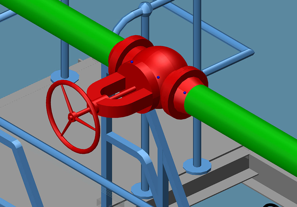
M4 PLANT has various view functions that make it convenient and easy to navigate within the 3D environment. There are zoom tools that can be used to enlarge or shrink individual areas. The mouse wheel can also be used for normal zooming. Users can also zoom-in on an individually selected object. In addition, the individual enlarged areas can be saved as views. Users can then always open these while editing.
Multiple views
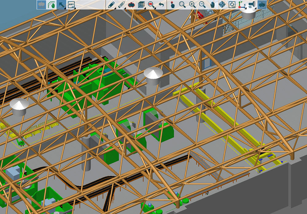
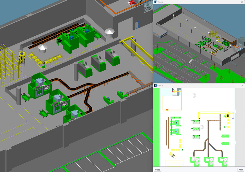
Individual views during the planning phase can be saved in M4 PLANT. The viewing angle and the zoom factor of the view are maintained. Individual views can be invoked again during the course of planning to work further on these points and or to present specific areas of planning.
Showing and hiding geometries
Thanks to flexible view functions, individual objects, complete groups or even maintenance groups can be shown or hidden in M4 PLANT. Thus, a user can concentrate only on the currently relevant area of planning without affecting other planning areas. Presentations can also concentrate only to one planning area. In addition, there is an option to hide individual areas to increase the software performance during the editing process.

Transparency, cutting plane and wireframe representation
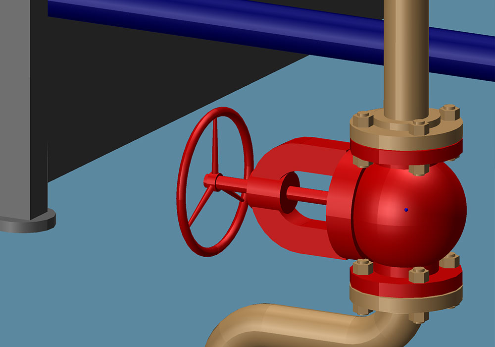
Individual objects in M4 PLANT can be made transparent to increase the overview in the extensive 3D planning environments. The user can set the level of transparency. As a result, even the objects behind a wall can be made visible. A cutting plane, which hides the currently visible 3D model from this plane onwards, can be added for the entire plan. In addition, individual objects can be shown in a wireframe representation that allows users, unlike the transparency option, to select even the objects or connection points behind or in the model.
Detail levels
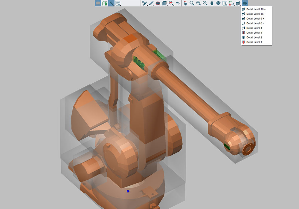
All 3D models or catalogue components used in M4 PLANT can be represented in different detail levels. The system has five different detail levels for this purpose. In the first detail level, the user can define essential free spaces for an object that need to be considered at the time of a collision check. The space required for the general collision check is defined in the second detail level. The model or the components can be shown with different details in the three subsequent detail levels. The highest level is typically used for showing the maximum number of details.
Selection functions
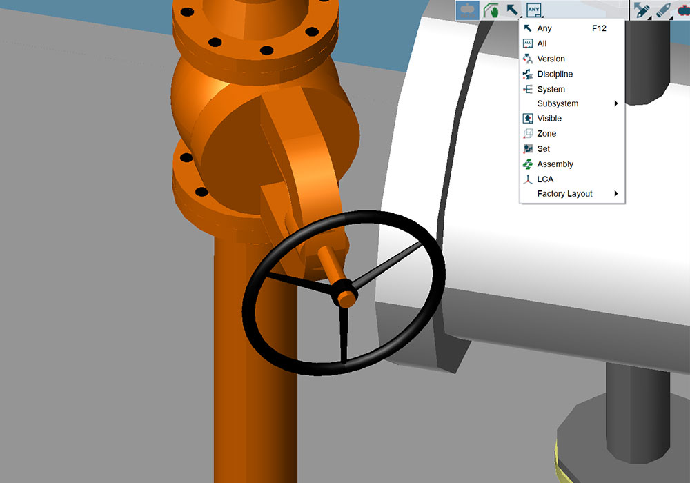
M4 PLANT has different selection tools for conveniently selecting individual elements in a drawing. The standard selection tool lets users choose individual elements or element groups within a certain area. In addition, they can use filters to select only the individual maintenance groups, systems, zones, sets or 2D layouts.
Multiple selection
