Integration with 2D data: The 2D & 3D Functionality
M4 PLANT – Plant Design and Factory Layout Software
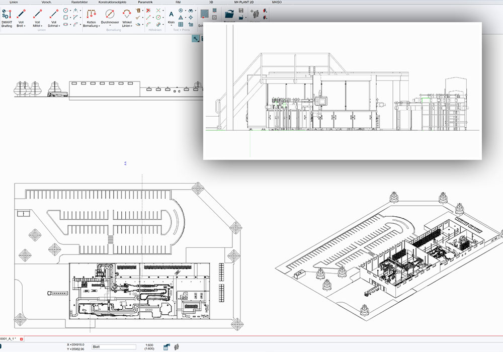
Importing 2D layouts in the 3D environment
M4 PLANT has a complete 2D functionality. It can be used to import or create 2D drawings in the form of building floor plans and layouts. In a 2D layout, the user can decide which elements should be made visible in 3D as well and where they should be located in the 3D building and installation plan. In 3D, the corresponding 2D geometries are loaded at the prescribed position and can thus be used for the orientation or placement of components.
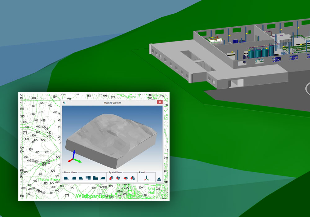
3D premises modelling from the 2D premises data
The additional 3D Terrain module in M4 PLANT can be used to generate detailed 3D premises models from the 2D premises data. The associated 3D model is automatically generated from the height texts stored in the premises plan. Additional functions in the 3D Plus additional module can be used to prepare detailed calculations for premises models and to calculate the volume of the earth to be engraved for the foundation. Both modules can be ordered in addition to the standard packages.
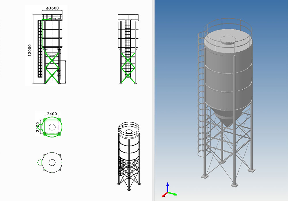
Generating 3D models from 2D data
The 3D modelling functions in M4 PLANT allow users to create a 3D model from the 2D drawings of a machine or a tank. Different 2D views of components are supplemented with 3D contour lines and provided with a depth in another view. As a result, detailed 3D models for further planning can be generated from the 2D stock or supplier data in the shortest possible time. In addition, models can be supplemented with additional detail levels, colours or connecting points. Versatile 2D editing tools allow a quick adaptation of created reference drawings.
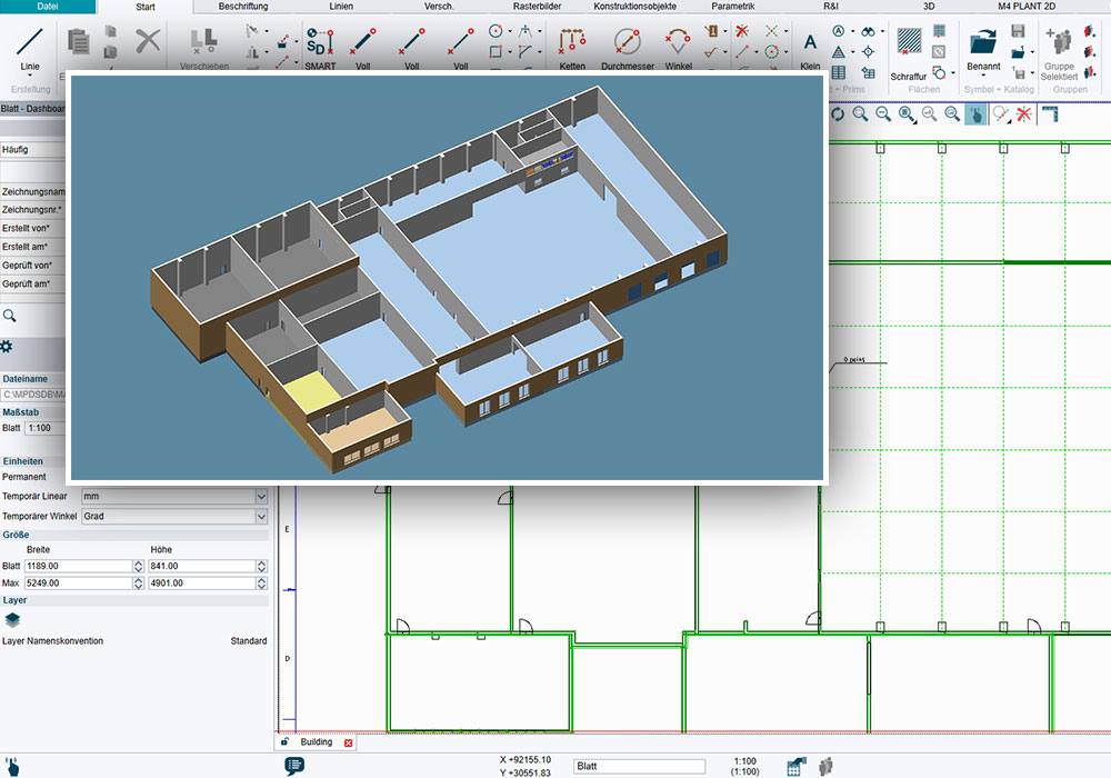
Generating 3D building models from 2D building plans
Device data is often available in the form of 2D building drawings or layouts. Based on the 2D data, 3D building models can be quickly and easily generated in M4 PLANT from 2D drawings. Geometries for the foundations, walls or columns in 2D must be selected and provided with additional information regarding the height of the element. New walls or building elements can be drawn quickly, easily and in detail. When switching over to the 3D environment, all detailed elements in 2D are automatically generated as a 3D model.
2D layouts as the basis for the 3D installation plan
At present, majority of installation plans are prepared as the 2D layout. M4 PLANT supports 2D-based generation of 3D installation plans. 3D models in the form of symbols can be placed on a 2D layout of a company or a plant. The 2D symbols are simply linked with the imported 3D models such as machines or 3D catalogue components like conveyor belts. When switching over to the 3D installation plan, these are updated and the corresponding components from the layout are automatically loaded at the corresponding point in the 3D layout. All changes are interactively synchronised in 2D and 3D. Owing to this technology, an integrative 3D installation plan can be generated without interruptions of medium and extremely large layouts can be prepared in 3D in a short time. These can be used for comprehensive plant demonstration for customer presentations. In addition, an interactive walk-through with desired camera movements, wherein an overview of the plant is given, can be created quickly.
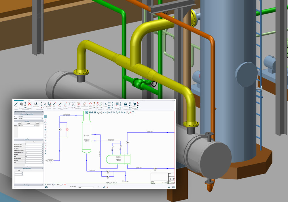
Integration with P&ID data
The stored information of a flow diagram creating using the P&ID module of M4 PLANT can be used as the basis for the 3D pipeline planning. A pipeline can be selected in the P&ID drawing and inserted in the 3D environment. The system automatically fills the corresponding dialogue boxes with the information received from the P&ID flow diagram. Models are pipeline strands are named such that they directly match. M4 PLANT also detects the connecting points of the model to which the pipeline should be connected and also detects the corresponding pipelines. Likewise, individual parts of a pipeline such as reducing connectors or valves can be positioned in an P&ID-driven manner. The user always gets a precise overview of already placed components and the components that are yet to be placed.
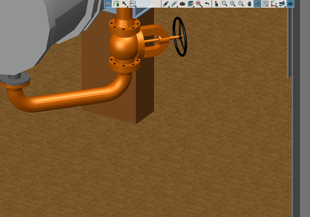
Textures
In M4 PLANT, the planning can be supplemented with individual textures. These can be used to represent signs or design floors and façades realistically. Layouts, which are only available in the form of graphics, can thus be imported in the plan.
Deriving 2D detailed drawings
M4 PLANT can be used to derive detailed 2D drawings from the complete 3D project, from individual areas or individual 3D components. The user can simply export the current 3D view as a 2D drawing and specify further details in it accordingly. Naturally, even a comprehensive 2D drawing with multiple views can be derived from the 3D planning environment. Extensive dimensioning and lettering tools are provided to users to add details to the drawing. The entire process is supported by intersection planes that ensure a better overview of the plan for individual views.
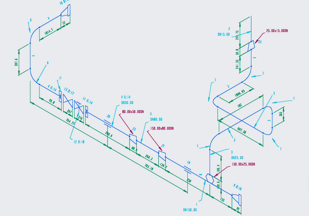
Creating pipeline isometric views
Thanks to M4 ISO, M4 PLANT has a completely integrated solution to create pipeline isometric views that are not-to-scale. The intuitive software uses pipework data from M4 PLANT to automatically create 2D pipe isometric drawings, along with complete bills of material and pipe cut-length and spool lists for fabrication and transport considerations. M4 ISO allows design engineers to include a 3D view of the relevant pipe segment with each isometric drawing, providing a welcome visual aid for fabricators and installers alike.