Piping isometric drawing – Overview, tips and downloads
The piping isometric drawing is an important part of plant engineering. They are used for the documentation and production of complex pipework. The clear advantage of a piping isometric drawing is its simplicity and symbolic representation of pipework, which allows it to be read quickly by all project stakeholders. But still some questions remain:
What is a piping isometric drawing?
A piping isometric drawing is a technical drawing that depicts a pipe spool or a complete pipeline using an isometric representation. The drawing axes of the isometrics intersect at an angle of 60°. Although the pipeline is accurately dimensioned, it is deliberately not drawn to scale and therefore does not correspond exactly to a real pictorial illustration of the pipeline. However, the piping isometric drawing enables the documentation of even long pipelines on a single drawing sheet. The representation of the pipeline in the isometrics corresponds to the exact route of the pipeline through the system or building.
Piping isometric drawing
A piping isometric drawing is usually created on a DIN A3 or A4 drawing sheet (portrait or landscape format), which correspond to the standards of a technical drawing. In addition to this, a piping isometric drawing includes a north arrow or coordinate system that shows the exact orientation of the pipeline in the system. For simple pipelines, the isometrics can be drawn using a single drawing sheet. For large systems with longer pipe runs and many components, these are divided into several contiguous drawing sheets for easier readability. For manual drawings, there is suitable drawing paper with isometric auxiliary lines. It is much easier to use piping isometrics software that already includes the necessary symbols and supports all standards.
Components of a piping isometric drawing
- Pipelines are shown as simple lines in a isometrics piping and the labelling of the lines is achieved using texts. Individual valves, welds and
- connections are illustrated using standard symbols.
- The exact lengths and slope of the pipes are defined using dimensions and gradient cross-hatching.
- In addition, an piping isometric drawing can contain further information about the components it contains by means of text annotation.
- Furthermore, a piping isometric drawing can contain parts lists, welding lists and bend tables.
How to create a piping isometric drawing
Here you will be shown the individual steps on how to create a piping isometric drawing. We will show you the manual and the automatic way to create piping isometric drawings.
Tip: Generate the piping isometric drawing completely automatically
With the help of suitable software, you can also have your piping isometric drawing created completely automatically. The only prerequisite for this is that you have created the pipeline in advance in a 3D pipeline construction system, such as M4 PLANT. It is important that you can export a PCF file from your system that contains all the relevant information about the individual pipelines. You can also learn how to design pipelines very easily in 3D using our piping design and piping isometrics video tutorials for M4 PLANT.

Here you can create complete piping systems in 3D and then automatically generate fully-dimensioned piping isometric drawings for all of your pipelines at the touch of a button. The piping isometric drawings generated contain all the information needed for fabrication including parts lists, welding lists and bending tables. If required, the system also outputs the bending tables as a file, which you can then use directly for NC pipe bending.
Create a piping isometric drawing automatically
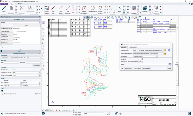
Here we show you the automatic way to generate a piping isometric drawing if you do not use M4 PLANT but your own 3D pipeline design system. First, export the pipelines as PCF files. Then open them in the M4 ISO FX piping isomertics software. Now you can convert these PCF files into fully-dimensioned piping isometric drawings. The software generates all drawings, parts lists and tables for you completely automatically in just a few seconds.
Create the piping isometric drawing manually
Here we show you the manual way to generate piping isometric drawing.
1. create a drawing sheet for isometrics
First create a drawing sheet in DIN A4 or A3 and activate the isometric grid. You can simply use CAD software such as M4 DRAFTING for this. This also already contains suitable drawing templates and the possibility to use an isometric grid. Also draw in the coordinate system or the north arrow here to determine the alignment of the pipeline in the overall system.
2. draw the route of the pipeline
Second, draw the pipeline with the help of simple lines. When using software, it is best to draw the entire route as a single line. This is because if valves or other piping components are added later, the pipeline can still be easily edited after drawing. The individual lengths do not have to correspond to the real physical pipeline, they only have to be drawn in such a way that the isometrics is legibly depicted on the sheet. The line corresponds to the centre line of the pipeline. Make sure to draw in the bends of the pipe bends directly. Pipe slopes or gradients must be marked separately and dimensioned later. You can also draw in the welds with the help of a point symbol.
3. draw in valves, flanges and other details.
Now you can add further components to the pipeline, such as valves, flanges or reducers. These are drawn on the lines in the form of isometrically aligned symbols. If you use software such as M4 DRAFTING at this point, you can use your own symbols for this representation or even import symbols. You can also create your own individual symbol libraries for isometric generation.
4. dimension individual parts of the pipeline isometrically
Now draw isometrically aligned dimensions for the pipeline. The individual dimensions must either correspond to the measurements for an existing pipeline or correspond exactly to the new pipeline design. Here the exact distances of the individual centres to each other are defined. Gradients or slopes must be dimensioned separately. CAD software such as M4 DRAFTING also provides the appropriate tools for isometric dimensioning.
5. define individual components and create a parts list
Before creating the piping isometric drawing, you will have already prepared a specification for your project which details the components that may be used in the project. Now you add notes to the piping isometric drawing to precisely speficy the piping components used in the pipeline. Alternatively, you can draw a parts list table of the piping isometric on the drawing which lists all the components used. Here, too, software supports you with note or table tools.
This is the manual way to create a piping isometric drawing. It is better to use CAD software, such as M4 DRAFTING, which can simplify many of the drawing steps here.
Downloads: Software and templates for creating a piping isometric drawing
You can try out all the software packages mentioned here free of charge. With M4 DRAFTING you can create piping isometric drawings manually using your own symbols. With M4 PLANT you can design your pipelines directly in 3D and then create the corresponding piping isometric drawings ready for production in seconds with just the push of a button. And with M4 ISO FX, you can take PCF files exported from your own 3D piping design system and convert them into piping isometric drawings in a few seconds, fully automatically.
A 3D piping design system for designing your pipelines in 3D and documenting them with fully automated isometric generation.
Uses PCF files from your 3D piping system to generate fully automated piping isometric drawing with all associated data.
Conclusion: Take the modern route to piping isometric drawing generation
Even if you prefer the manual way of creating piping isometric drawings, it is worth taking a closer look at the modern tools.
Create a piping isometric drawing: This is how it works
A 3D design is the most accurate and visual way to design your pipework. When your design is complete, you not only get all your associated 2D layout drawings and parts lists generated automatically, but you can also generate all required piping isometric drawings at the push of a button, right first time. This is a huge time-saver that allows you to complete more projects in an even shorter time with a high level of design quality.
Do you need more information or advice? Then simply contact us and together we will find the best solution for generating your piping isometric drawings.

FAQ: Frequently asked questions & answers about isometrics
An isometric view is one of the basic drawing projections. For this, three-dimensional representations are developed in a simple way from a two-dimensional drawing. In the projection, the isometric view represents the two ground plane axes each at 30° to the horizontal baseline. The height axis is entered perpendicular to this. This is a simple form of geometric representation in which all three spatial axes have the same length and division. The three simultaneously displayed views of the body (front view, top view, side view) are equally weighted in isometrics.
A piping isometric drawing is a simplified representation of a pipeline system. It contains the dimensions of the pipeline route and the position of the piping components in isometric projection. The pipelines with all components and fittings are shown in an isomertic drawing with a 30°/30° grid. Piping isometric drawings are preferably created using a CAD system. A A piping isometric drawing is always drawn not to scale.
A piping isometric drawing can be drawn manually on a sheet of paper (isometric paper) or with the help of CAD software. The use of CAD software offers many advantages because the work involved is greatly simplified by standard symbols and clever editing tools. In addition, piping isometric drawings can be generated completely automatically from a 3D model of the pipeline using specialised software packages, such as M4 ISO.
A piping isometric drawing is a simple representation of the pipeline, which nevertheless contains all relevant information and dimensions. The piping isometric drawing is used both for documentation and for the production of the pipelines. This is because it enables a pipework manufacturer to determine exactly how the pipeline will run and exactly which components the pipeline contains.
Piping isometric drawings are deliberately drawing not to scale. This is so that even very small closely packed areas of the real physical pipeline, can be clearly shown spaced out on the piping isometric drawing. The dimensioning shown on the piping isometric drawing are what counts and show the actual true length of the pipes and positions of the piping components.
No, piping isometric drawings are prepared using a specialised isometric projection in which all piping components are shown using standard symbols, and all pipes are shown as simple lines. The drawing does not contain perspective views of the pipework.