Technical drawing: basics, overview, and a recommendation
Technical drawings can be thought of as being the universal language of engineers and are a key part of technical communication.
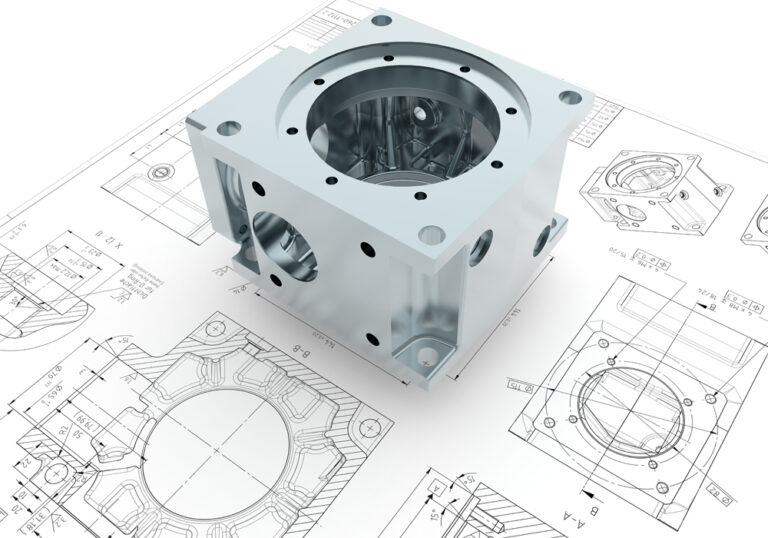
A technical drawing is not only a representation of a product, a plant, or a component, it is the way ideas, information, and complex technical matters are communicated as a universal engineering language.
Whenever products are designed, technical drawings are necessary. This is because although designers have many good ideas, they cannot develop, produce or sell the products themselves. Collaboration with others is necessary and so ideas need to be communicated as clearly as possible. A technical drawing provides a way for the entire production team to communicate, as well as being a means to visually describe a product design and all of its salient details. To use technical drawings effectively, specialist knowledge is required to understand the symbols, rules, and standards used. In addition, knowledge of the software used to create the drawings is required. This article provides an overview of technical drawings.

What is a technical drawing?
First, exactly how is a technical drawing defined? It is primarily a written document that serves a technical purpose and is a means of communication between the design and manufacturing departments. Designers must be able to represent their ideas in the form of a drawing and the production engineers must, in turn, be able to understand this drawing correctly and use it for manufacturing purposes. An engineering drawing typically contains a detailed representation of a component or assembly. They are used for the design and manufacture of entire machines, for example. A drawing will contain scaled views together with dimensions, manufacturing tolerances, and any other necessary annotations. Drawings may also show complex functions and the construction methods for individual parts and assemblies. In addition, technical drawings form an essential part of the technical product documentation.
Overview and basics
Technical drawings must be clear and understandable by the end users for the intended purposes. To ensure that technical drawings are complete and unambiguous, a number of drawing standards, such as those produced by the DIN standard of the Deutsches Institut für Normung e.V. (German Institute for Standardization), are used to regulate the content of drawings. These standards bear the abbreviations DIN, DIN EN, or DIN ISO and control many aspects of the drawings, such as the relative placement of elevations, the thicknesses of lines and the size of texts that can be used, and the appearance of dimensions and tolerances. It is important that technical drawings are always created in compliance with the relevant drawing standards, and are above all, complete.
What is a technical drawing?
A technical drawing is a detailed illustration of existing or newly designed components which are required, for example, for the manufacture of complex machinery. It contains scaled views together with dimensions and notes to fully define individual parts and assemblies. It is primarily a written document that serves technical purposes and acts as a means of communication between the areas of design and production.
Standards for technical drawing
Various different international standards exist for technical drawings (e.g. DIN, ISO, BSI, JIS, ANSI) and their usage varies from country to country. For example DIN is prevalent in Germany, and ANSI is the norm in USA. Modern CAD systems enable technical drawings to be created using a range of international standards and units of measurement. Whether a component is to be manufactured in the USA or China, the technical drawings can be standardised for each country so that they can be easily read and used. It is therefore essential that technical draftsmen adhere to the applicable standards. Otherwise, the design loses its validity and can be misinterpreted, leading to the component being incorrectly manufactured. Today, CAD software can also be used to convert between different units of measurement, and translate text into other languages, so that the international exchange of drawings is even easier.
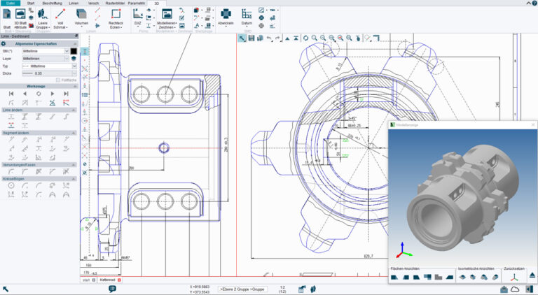
The creation of technical drawings
Before the advent of computers and sophisticated office technology, technical drawings were drawn by hand on special paper fastened to large drawing boards. The originals had to be carefully stored and copied for later use. Thanks to CAD software, this process is now much easier. CAD drawings can be easily created on a computer whenever required, and most importantly, stored digitally. If a drawing is needed in paper form, it can for example, be automatically scaled and printed on to paper at different sizes such as A3 (420 x 297 mm) or A0 (1,189 x 840 mm). The right CAD software enables even non-professionals to create a clear plan with little effort. Users quickly learn the ropes thanks to the supplied tutorials and can create a usable drawing after just a few hours.
Choosing the right format
The format plays an essential role in the later uses of a technical drawing. Size is of the utmost relevance not least when printing on paper. Here, for larger projects, attention must be paid to the maximum roll width of the printer. Most large format printers print up to a width of 910 mm and a length of up to 3,000 mm. The production of a plan in DIN A0 is therefore possible without any problems. But not only DIN formats are in demand. Arbitrary sizes allow the user greater flexibility to accommodate the data and explanations on the technical drawing.
The scale of a technical drawing is key
It is not uncommon to encounter drawing scales such as 1:50 or 1:100. The scale determines how big the design physically appears on a drawing. As a general rule, products cannot be drawn full-size because this would result in gigantic or tiny technical drawings in many cases. Depending on the size of the component, it makes sense to represent it at a convenient scale, enlarged or reduced. In a technical drawing, each component must be drawn to scale and the scale used must be indicated on the drawing. With special conversion formulas and tables, the components can be shown reduced in size and subsequently read and implemented more easily by the designer.
The Drawing frame and title block
The drawing frame and title block (also known colloquially as the drawing header) are standardised in a technical drawing. EN ISO 7200 regulates the design, which states where the title block must be placed and how the frame is to be drawn. The new EN ISO 7200 regulation replaces the DIN 6771-1 standard, which was much stricter. Designers now have more freedom in creating technical drawings and can adapt them to the individual needs of their customers.
International Organization for Standardization (ISO) >>
However, there are still a few things to keep in mind to ensure that the drawing is correct. The title block is always located at the bottom right of the plan. The frame is 180 mm wide. This is mainly for later processing of the plan when it has been plotted. When folding to DIN A4 with a stitching strip, perforated edge, or similar, the drawing header and legend are always clearly visible. There are no longer any regulations regarding height or column width. Only a recommendation of the number of characters is given.
The following mandatory fields are important and must be present on every technical drawing. Additional fields are optional if required.
- Legal owner, e.g. company
- Part number
- Date of issue
- Section/sheet number
- Title
- Approving person
- Creator
- Document type
Dimensioning a technical drawing
The correct dimensioning of individual components is essential, because only then can they be manufactured. DIN 406-10 and DIN 406-11 contain the basic rules for dimensioning technical construction drawings. Dimension values, dimension lines, auxiliary dimension lines, and dimension arrows are important for correct dimensioning. The dimensions describe the size, shape and position of a component, e.g. its length, height or diameter. Dimensions are always specified in millimetres (mm) and must fully and unambiguously describe all aspects and features of the component. The dimensions can be function-related, production-related, or inspection-related.
Functional dimensioning
Function-related dimensioning is necessary for the functional performance of the component or assembly. The focus here is on the optimum cooperation and fit of the individual parts. Furthermore, specified tolerances ensure trouble-free assembly.
Production-related dimensioning
As the name suggests, production-related dimensioning deals with production. The dimensioning used depends on the manufacturing process. The dimensions must be usable here without conversion. In addition, dimensioning from reference datums is useful.
Inspection-related dimensioning
Inspection-related dimensioning involves the direct inspection of dimensional accuracy. Here, too, the dimensioning depends on the respective test method. The dimensioning must be usable without conversion. Furthermore, incremental dimensions are useful.
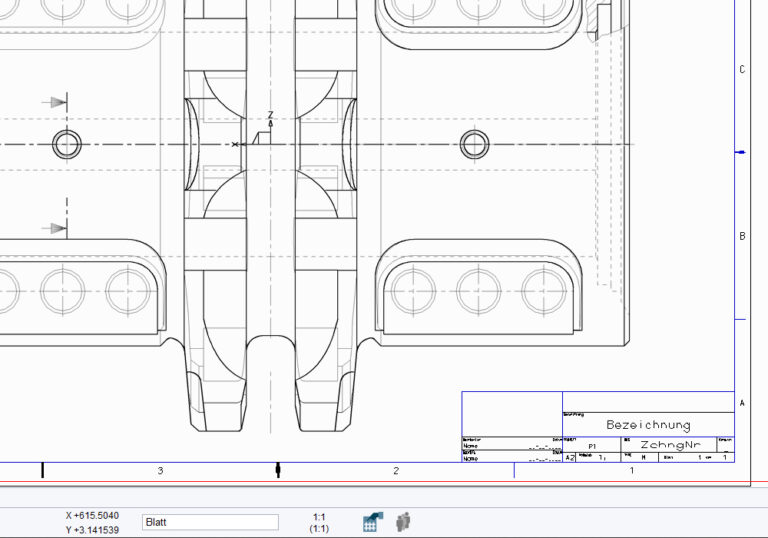
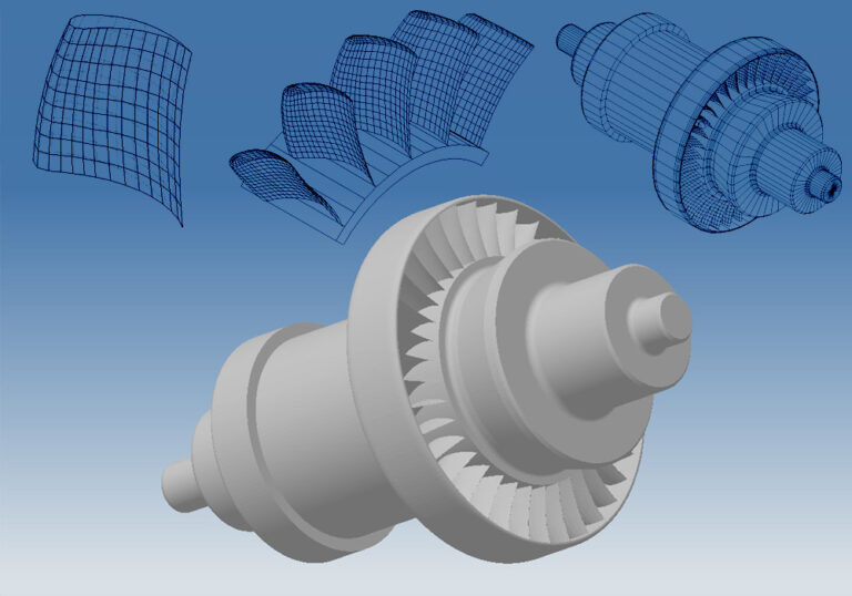
Views and sections
Different views are used for the representation of individual components. The views of a technical drawing describe the observation of a component from several directions. Here, for example, projection methods can illustrate the component from different sides. It is important that as many views as necessary are shown to clearly define the overall shape of the component. The front view should always be the most informative view of the assembly or the individual part and is also referred to as the main view. The most frequently used form of representation consists of front view, side view, and top view. The front view shows the component from the front, the side view shows it from the left and is drawn to the right of the front view, and the top view, which shows the object from above, is drawn below the front view.
Sections also play an essential role in the representation of a component. A distinction is made here between full, half, partial, and step sections. With a full section, the entire front half is cut away and removed so that the back half is visible. With the half-section, only half of the front side is removed. If the partial section is used, then only one piece is removed. For example, this can be a quarter of the front piece or even a part of the hole to make it visible. To show special details, a step-section can be used. This differs from the half and full section. The depth of the section is variable and does not have to be in a single plane, as with the two previously mentioned forms of section. The section surfaces are marked by hatching. These are narrow solid lines that run parallel, at the same distance, and an angle of 45 degrees to the main axis of symmetry of the component. Different styles of hatching are also used to visually differentiate between several parts within a sectional view.
Caution: Some parts may not be sectioned. These include rotating parts such as shafts (exception: bushings and shafts with a pronounced inner contour), journals, axles, bolts as well as standard parts (washers, nuts, screws, rivets, etc…).
Typical markings found on a technical drawing
To convey certain meanings, different types of markings are used in CAD language. For example, there may be a box around a dimension. This expresses that no tolerances are permitted. Permissible deviations must also be indicated for each value, insofar as they are possible and necessary. This has the advantage that production can be carried out more cheaply, as coarser, machine processes are made possible. Tolerances, for example, are represented with a +/- 1. This means that the side or the diameter may deviate by one millimetre upwards or downwards.
What is the purpose of notes on a technical drawing?
The right software provides space for notes in the technical drawing. Notes are often necessary to describe the design and to remind oneself of one aspect or another. Notes can be created quickly and positioned in the right place. This way, no information is lost and users have all relevant information in one place. Other users can also benefit from the notes, where, for example, several departments in a company are working on a technical drawing.
Symbols for technical drawings
Information in technical drawings can be expressed by different symbols. There are different types of symbols:
- Font symbols
- Punctuation
- Digits
- Surface processing symbols
- Connection symbols (welding symbols, rivet symbols, screw symbols, etc.)
- Roughness, dimensioning, and tolerance symbols
- Component symbols (screw, spring, rivet symbols, etc.)
- Assembly symbols (bearing, motor, gearbox symbols, etc.)
- Machine, device, apparatus symbols
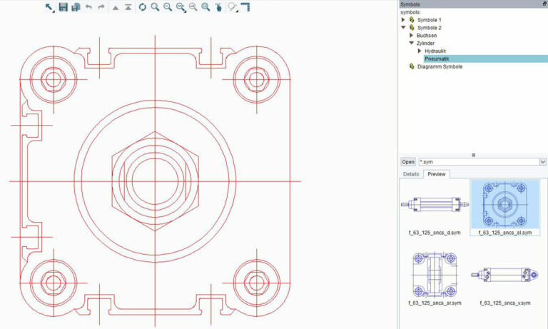
Certain symbols may only be used unchanged in their dimensions (welding symbols, surface treatment symbols, etc.). Other symbols must be adapted in their dimensions to the component. CAD systems will have symbol libraries from which the user can select the symbols relevant to their drawing. A large selection of symbols can be found in the M4 DRAFTING CAD software.
Whether CAD is used in civil engineering, mechanical engineering, electrical engineering or to create escape route plans, some symbols occur repeatedly. If a symbol catalogue is included in the software, symbols can be easily retrieved from the symbol library in the software. The intuitive selection of symbols guarantees trouble-free work and fast productivity.
The following symbols are important in mechanical engineering:
- component symbols (screw, spring, rivet symbols, etc.)
- assembly symbols (bearing, motor, gearbox symbols, etc.)
- machine, device, apparatus symbols
What is clear is that working with symbols can save time. Therefore, it is purely a matter of personal choice whether you decide to use symbols and thereby save time.
Symbols can also be used to define geometric tolerances in the technical drawing. There is a distinction between form tolerance (form deviation), alignment tolerance, positional tolerance (positional deviation) as well as concentricity tolerance. In this interaction, the symbol describes a geometric property. For example, straightness is represented by a straight line, roundness by a circle. A parallelogram is used for flatness. Features such as parallelism, perpendicularity, angularity, exact position, symmetry, concentricity, the total runout, and other properties can all be represented with the appropriate symbol. Special CAD programs offer many symbols with appropriate meanings. Finally, legends are often placed on the drawings to make the selected symbols understandable.
Certain machine elements (screws, cylindrical pins, feather keys, gaskets, etc.) are defined by standards and are therefore easily interchangeable. Other (more complex) machine elements are defined by standards in key properties such as the main dimensions and flanges. They are only interchangeable to a limited extent. These include machine elements such as bearings, couplings, gears, and shafts. CAD software provides specialised tools for architecture, mechanical engineering, electrical engineering, and more. It includes symbol libraries with intelligent objects and standard parts.
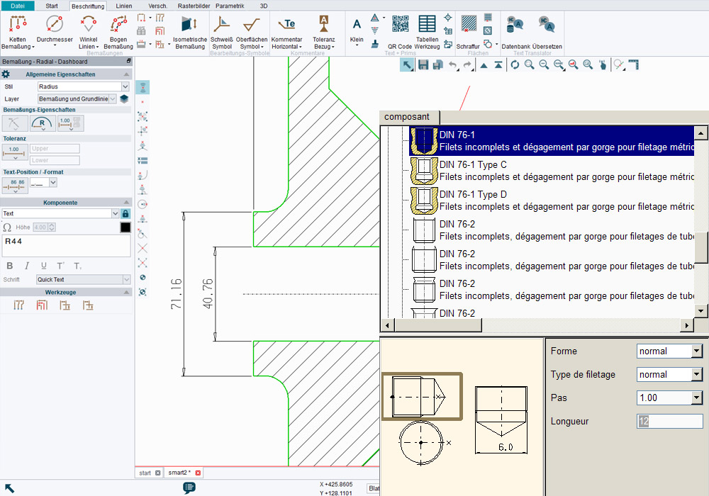
Standard parts for technical drawings
Standardised machine elements, or standard parts for short, are the best design solutions. As purchased parts, their use leads to savings in design and production. Standard parts and standard components are usually made available in catalogues in the CAD system. Since standard parts such as screws, nuts, bolts, pins, etc. are not manufactured by the user but are purchased ready for installation, the representation in the CAD system is essentially limited to the standardised connection conditions. Manufacturer-specific differences in the standard parts must not have any functional effects. In the design of machines and systems, the design and manufacture of simple parts and components often costs a lot of time and results in higher costs. Both can be avoided if designers use standard parts and standardised components. The M4 DRAFTING CAD system offers a wide range of these components. For designers, this means even more flexibility.
Simply select CAD standard parts in the catalogue
CAD data for all products are included with the installation. All CAD models are static, so not only is there no need to draw the components, but also to configure them. Manufacturing costs can be significantly reduced if as many standardised components as possible are used. Designing with standardised components has many advantages. For example, solutions implemented with standard parts offer lower design and manufacturing costs, and assembly can also be quicker. The usual time-to-market phase can be significantly shortened by using standard parts and especially for standard applications. Anyone with a concrete idea of the type and scope of components to be used can find them in M4 DRAFTING.
Designing with standardised components has many advantages. For example, solutions implemented with standard parts offer lower design and manufacturing costs, and assembly can also be quicker.
Templates for technical drawings
Templates enable users to work even more effectively. Templates with the most important content elements for CAD drawings ensure work is standards compliant and saves time during creation. Templates can be individually adapted by users to company-specific specifications and formats and ensure that everyone is working from the same base. For companies that want to work with a uniform CI (corporate identity with the same logo, font size, etc) or the same dimension specifications, this way of working is particularly relevant and enormously timesaving.
Programs for the creation of a technical drawing
Today, either CAD programs or technical drawing programs for 2D and 3D plans are required for the creation of technical drawings. The type of software needed depends on purpose and frequency of use and there are a variety of applications available on the market that provide different options. Some of them are freely available to users, such as M4 PERSONAL. These programs vary in their structure, ease of use, and scope. It is important that software is easy to understand and leads the user intuitively when creating and editing plans. In this way, every user quickly achieves the desired result.
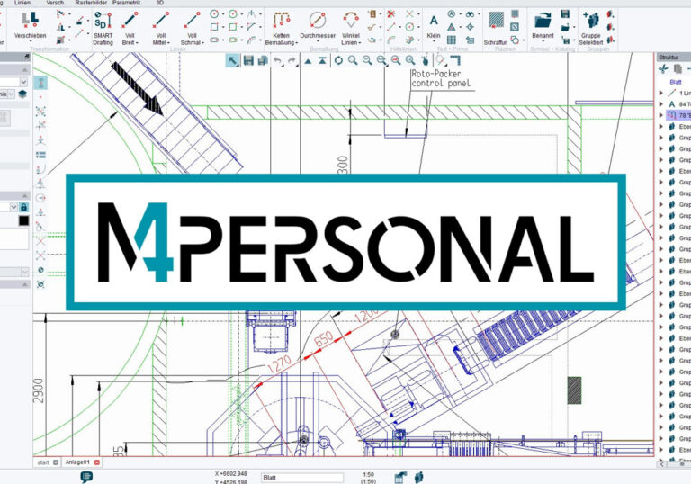
M4 PERSONAL (for private users and small businesses)
Using M4 PERSONAL brings many advantages to users. It is a powerful 2D/3D CAD package that is used worldwide which makes creating and editing technical drawings child’s play. 3D models can also be created with the program. In addition, the software is available for use free of charge. It is primarily intended for private individuals and small businesses.
Users benefit from various video tutorials to help them get started. M4 PERSONAL supports all common units of measurement as well as dimensioning standards. Styles and templates are also customisable.
DWG and DXF – import and export
M4 PERSONAL offers many interfaces. For example, users can open and edit DWG and DXF files and convert them via the available eServices. The export function is particularly useful and flexible for small companies. They can both import and export DWG and DXF formats via eSERVICES. CAD drawings can thus be saved directly as DWG, DXF, or PDF for further use or forwarding. All drawings converted in this way can be used commercially and without restrictions.
3D formats are also available. You can upgrade to M4 DRAFTING for Business at any time and benefit from even more features.
To complete the overall experience, users have help centre and documentation options at their disposal. They can receive suggestions to help solve any issues that may arise. The package offers its users a KDB (Knowledge Database). This is constantly growing thanks to a large and growing number of users.
M4 DRAFTING (for companies)
M4 DRAFTING is used to create and edit CAD drawings. Whether 2D or 3D, the software sets no limits for its users. The process can be learned quickly and offers high performance. Thanks to various automation tools, recurring workflows can be optimised, so that users can work much more productively. Common CAD formats such as DWG, DXF, and DGN are supported as standard. Plans and models can be opened and edited without difficulty. Various 3D formats are also compatible with M4 DRAFTING.
Whether for single workstations or network use, M4 DRAFTING is flexible and individually scalable to the different needs of its users. The software itself can also be customised so that users can easily achieve the desired results. The M4 software package is used worldwide and supports standard units of measurement and dimensioning. In addition, it supports users through tutorials to help them get the full benefit of the 2D and 3D software. M4 DRAFTING will revolutionize the first step in the creation of a component or group of components with standards-compliant, clear, and unambiguous technical drawings.
Conclusion
Technical drawing is more than just drawing pictures. It is a language, a graphical language that communicates ideas and information and has evolved into a means of communication that is more precise and unambiguous than any other language. Accurate technical drawings are the foundation for the production of components.
To create a flawless, standards-compliant technical drawing, the right CAD software is invaluable. Users enjoy a wide range of attractive offers, some of which are even available free of charge. Whether the software is used by a company or a private individual, there is a suitable package available. Assistance and contact options make it easier to deal with questions and problems so that nothing stands in the way of producing a high-quality technical drawing for that world-beating component.
FAQ – Frequently asked questions about the technical drawing
A technical drawing is a detailed illustration of existing or newly designed components which are required, for example, for the manufacture of complex machinery. It contains scaled views together with dimensions and notes to fully define individual parts and assemblies. It is primarily a written document that serves technical purposes and acts as a means of communication between the areas of design and production.
CAD drawings are standardised by each country. Thanks to the CAD software used to digitally create engineering drawings, international units of measurement dimensioning standards and can be used. Whether the component is to be created for the USA or for China, engineering drawings are standardised for each country so that they can be easily read and implemented by each department. Today, CAD software can also translate individual units of measurement, representations or texts into other languages or standards, so that the international exchange of drawings is also possible.
It is not uncommon to come across drawing scales such as 1:50 or 1:100. The scale determines how big the design physically appears on a drawing. As a general rule, products cannot be drawn full-size because this would result in gigantic or tiny technical drawings in many cases. Depending on the size of the component, it makes sense to represent it at a convenient scale, enlarged or reduced.
The most frequently used form of representation consists of front view, side view and top view. The front view shows the component from the front, the side view shows it from the left and is drawn to the right of the front view and the top view, which shows the object from above, is drawn below the front view.
Either CAD programs or technical drawing programs for 2D and 3D plans are needed to create technical drawings. The scope of the software depends on the purpose and frequency of use. Different applications are available on the market. Some of them are available to users free of charge, such as the free CAD software M4 PERSONAL.