CAD programs: Complete overview and free downloads
A complete overview of 2D and 3D CAD programs with free downloads to get started with the right program directly
Nowadays, most manufacturing companies use CAD programs to develop new products and even to design entire production plants and factories. For many of these companies, sooner or later the question arises as to which CAD program is best suited for the tasks and challenges they face.
CAD programmes are used by almost all companies that need to plan a product, a building or a plant as well as create the corresponding documentation. These programmes are used both for designing new products and for detailed planning of complete production facilities and factories. Since a company often has to master various challenges with a CAD programme, the question always arises as to which CAD programme is best suited for the tasks at hand. Therefore, here is a complete overview of what CAD programmes actually are, what types of CAD programmes exist and what they can be used for.

CAD Programs – A short introduction
What exactly is a CAD program?
The abbreviation CAD stands for Computer-Aided Design. Design tasks are performed using a computer and a suitable CAD program. CAD programs are used to design products such as machinery, robots, and cars. Depending on the type of CAD software used, technical drawings (2D CAD) or 3D models (3D CAD) are produced, which are then used for product manufacturing.
Who uses CAD programs?

What is a CAD program used for?
What are the advantages of a CAD program?
CAD programs at a glance
2D CAD programs
Programs for creating two-dimensional CAD drawings and detailing them with dimensions, tables, images or notes. Can be extended by industry-specific modules.
3D CAD programs
Programs for the creation of three-dimensional CAD models, enabling better optimisation of components through different simulations or easier export for different manufacturing methods.
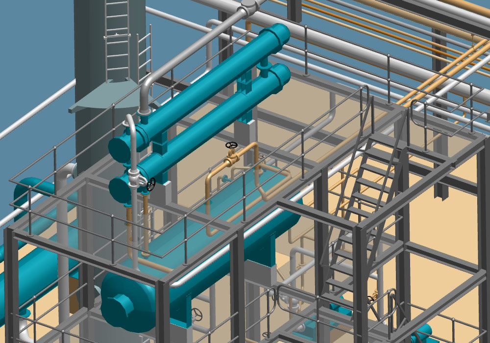
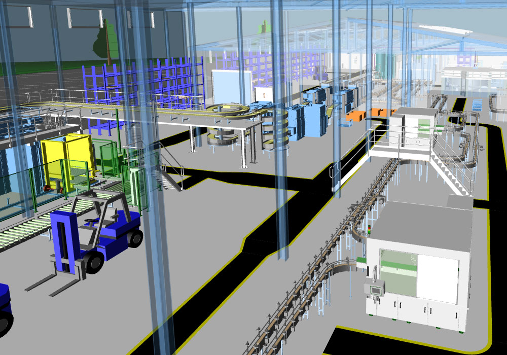
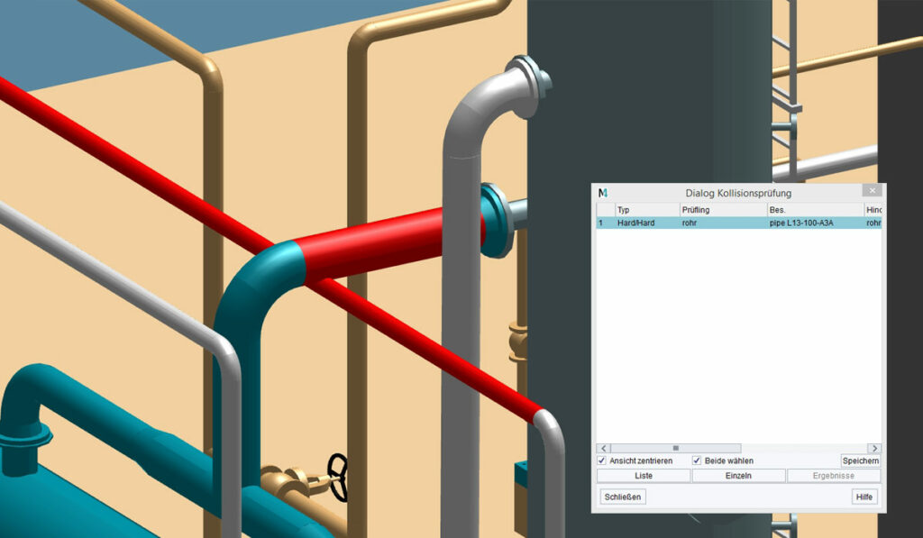
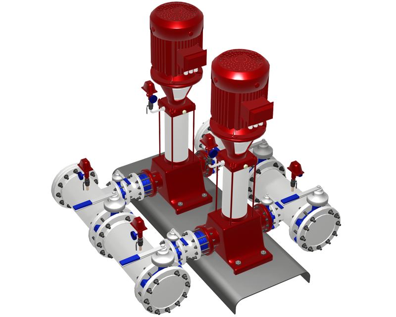
3D Plant Design Programs
2D CAD programs (2D design)
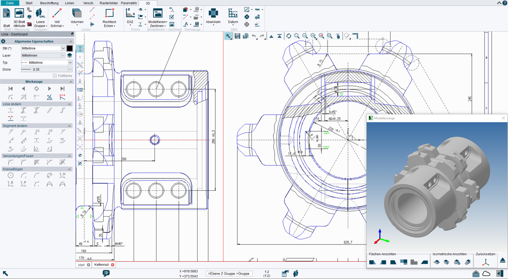
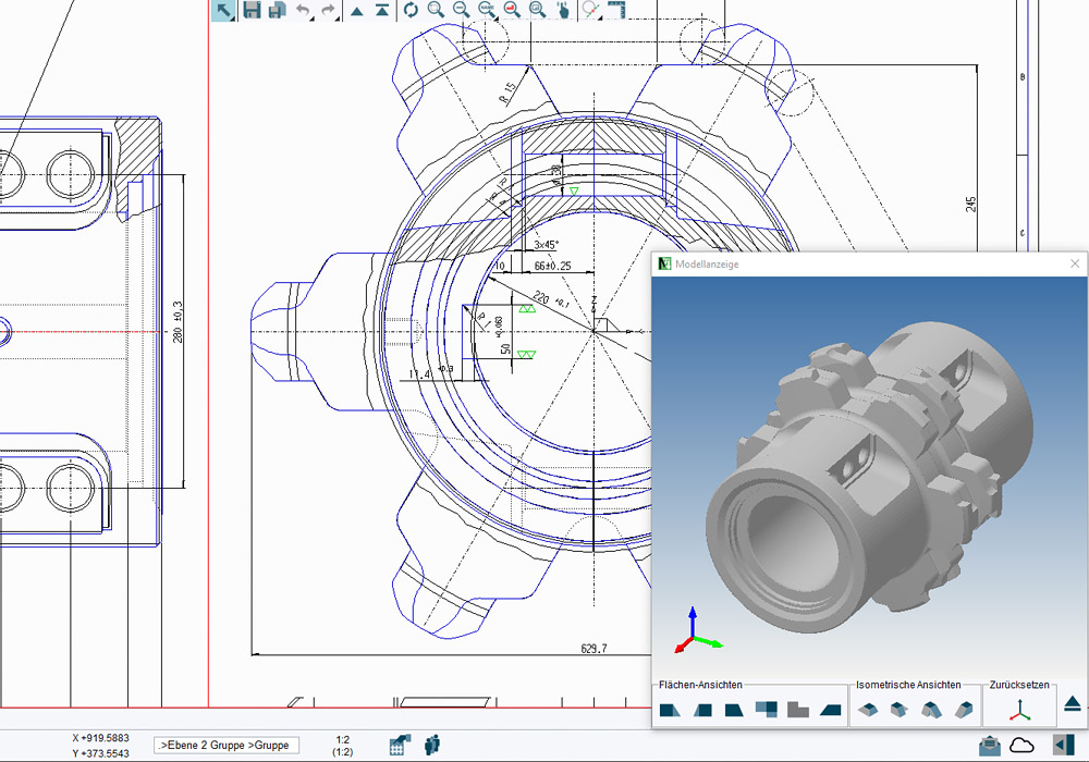
Free 2D CAD program
The freely available M4 PERSONAL 2D CAD program contains an extensive range of CAD functionality. The software is free for non-commercial use. However, if you wish to use the generated CAD drawings commercially, they can be converted into the popular DXF or PDF formats via an online service, which also authorises them for commercial use. Video tutorials are available for a quick introduction to this CAD program.
2D CAD program for companies
3D CAD programs (3D modelling)
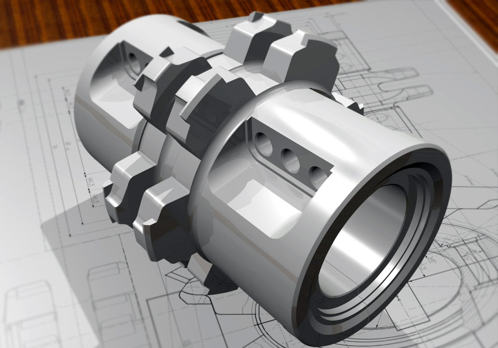
Top 3D CAD program
3D Plant Design Programs