What is a piping & instrumentation diagram and how can I quickly create one without errors?

The piping & instrumentation diagram is a highly important document for process plant design. Despite its simplicity, it contains a wide-range of detailed design information. But what exactly is behind a piping & instrumentation diagram?

What is a Piping & Instrumentation Diagram?

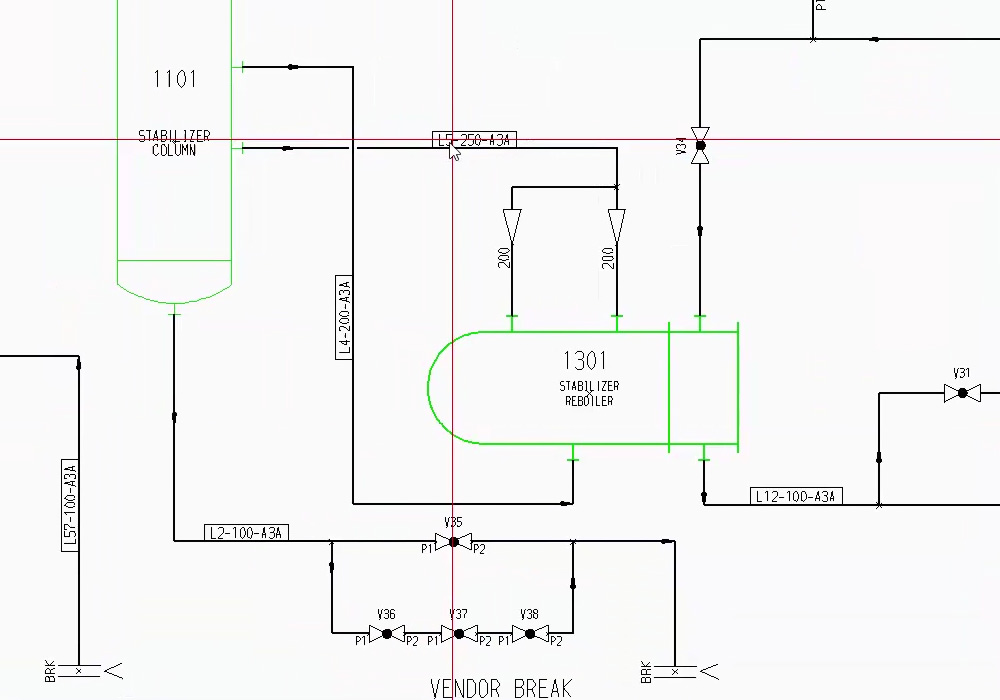
A Piping & instrumentation diagram is the basis for pipework design. Piping & instrumentation diagrams are used to schematically represent a design, and are usually created before any physical equipment design or layout takes place. All of the equipment and instrumentation required for a process is depicted using symbols, and any interconnecting pipework is represented using simple lines. Piping & instrumentation diagrams contain a considerable amount of detailed information about the design such as equipment tags, line labels, bore sizes, quantities and connectivity. But how can so much information be accommodated within such a simple diagram?

A P&ID is the basis for pipework design

Symbols – the aim is to achieve meaningful simplification

The use of symbols is fundamental to creating a piping & instrumentation diagram. Symbols must be simple and easy to remember, while at the same time clearly depicting the function of the equipment they represent. Frequently used symbols for equipment such as pumps, blowers and tanks will typically appear multiple times on a piping & instrumentation diagram. Each symbol is labelled with a unique tag number to ensure it can be unambiguously identified.

Making processes visible

Another design task is to show how equipment is connected. This is achieved using simple process lines to represent the interconnecting pipework. When complete, the piping & instrumentation diagram acts as an important reference document for all downstream design tasks such as equipment layout and the routing of pipework. It is also used to prepare parts lists to assist with choosing suitable components and for project costing purposes.

Create a piping & instrumentation diagram, but with which software?

Modern P&ID software packages offer a range of standard symbol libraries to enable piping & instrumentation diagrams to be quickly drawn up. The pipework between individual components is represented using simple process lines. Additional tools enable equipment, instrumentation and process lines to be uniquely labelled to ensure they are unambiguously defined. Although this functionality is included with most P&ID software packages, it does not guard against design errors.
“A piping & instrumentation diagram is a highly important document used for process plant design and contains a wide-range of detailed design information.”

Creating piping & instrumentation diagrams – Without Errors

One of the biggest advantages of modern software packages for piping & instrumentation diagrams is their ability to automatically check the entire design for consistency and errors during the drafting process. The latest P&ID systems generate a detailed list of problem areas and highlight them on the piping & instrumentation diagram. This allows the designer to quickly and easily make corrections and prevent the issues from affecting subsequent project phases.

The piping & instrumentation diagram: the basis for quotations

Piping & instrumentation diagrams are commonly used for preparing quotations, but far too often the calculations are still performed manually, and are therefore prone to human error. The latest P&ID systems automate this task by deriving parts lists directly from the piping & instrumentation diagram . The resulting lists are not only highly detailed and accurate, but can also be output in a range of useful formats for integration and use with other systems.

High level of design detail

Traditionally, piping & instrumentation diagrams contained only a limited amount of information about a design, but current P&ID software packages offer the capability to enrich piping & instrumentation diagrams with user-defined attributes to produce highly intelligent piping & instrumentation diagrams. Attributes can be assigned to equipment and instrument symbols, as well as process lines. Attribute values can either be freely specified by the user or constrained to set values. Typical applications include the specification of pressure ratings, sizes, materials, pipe contents, capacities and temperatures, the possibilities are almost endless. Attributes can be visible on the piping & instrumentation diagram, or hidden from view, but they are always available for output to automatically generated listings. This eliminates the need for additional documents and improves data re-use and integration with other company systems.

A modern system for piping & instrumentation diagrams

One software package that stands out due to its intelligence and sheer flexibility is CAD Schroer’s M4 P&ID FX. This system is highly affordable and has all the functionality you need to quickly and accurately create intelligent piping & instrumentation diagrams. Its extensive attribute capabilities and customisable parts list generation set it apart from other packages on the market, which often cost a lot more but do a lot less. It is also extremely easy to use, and is supported with video tutorials to help you get started. Piping & instrumentation diagrams are the basis for process design. They can be quickly and accurately created using modern P&ID software to ensure a high quality design.
Piping & instrumentation diagrams are the basis for pipework design. They can be quickly and accurately created using modern P&ID software to ensure a high quality design.

Embedding attributes in your Piping & Instrumentation Diagrams

FAQ – Frequently asked questions about piping schematic

A piping schematic is the basis of designing in plant and process engineering and is used to graphically depict the structure and function of a plant. All the apparatus and machines required for the processes are shown in it as a simplified, schematised illustration, not to scale.

Modern programmes for creating piping schematics typically offer standards in the form of symbol libraries as standard. This means that piping schematics can be compiled quickly and are already included in the software package.

When creating a piping schematic, the use of symbols is very important. The symbols should be simple, easy to understand and memorable, while at the same time indicating the function of the unit.
Modern P&ID systems offer automation here, deriving the corresponding parts lists directly from the flow diagram. These are not only extremely precise, but are also directly available in a suitable format for the spreadsheet, so that a quotation calculation turns out very detailed and accurate.

P&ID is the abbreviation for “piping and instrumentation diagram” and is a term from process engineering in plant construction. P&ID is often used in conjunction with a P&ID flow diagram, P&ID schematic, P&ID diagram or P&ID piping schematic.

Scroll to Top