

3D software for factory layout & plant design
Powerful Professional CAD software for your projects
Free 2D/3D CAD Software
P&ID Software for Intelligent Piping Schematics
Automatic Piping Isometrics for Fabrication and Installation
3D/2D viewer for CAD models and drawings
We develop individually tailored VR solutions
Virtual online meetings
Virtual Reality Viewer for 3D CAD models
Augmented Reality Solutions for Industry
AR-Viewer App for viewing 3D models in augmented reality
Augmented Reality (AR) for your product catalogs
From Parametric Symbols to Automated Drawing Generation
Colour Image Integration into CAD Designs
CAD standardised-part library for even faster design
Creating 3D Models without 3D Knowledge
Rapid generating and processing of 3D sheet-metal components
Software for Intelligent Piping and Process Schematics
Integrated drawing, document and information management
Interfaces and Integrations for ERP, PDM, PLM
We regularly create new tutorial videos
We regularly create new tutorial videos
M4 DRAFTING Package Overview
The software is supplied with an extremely flexible licence management module
M4 DRAFTING Customers in success
Updates, Online Support and Hotline
M4 DRAFTING Package Overview
The software is supplied with an extremely flexible licence management module
M4 DRAFTING Customers in success
Updates, Online Support and Hotline
3D software for factory layout & plant design
Powerful Professional CAD software for your projects
Free 2D/3D CAD Software
P&ID Software for Intelligent Piping Schematics
Automatic Piping Isometrics for Fabrication and Installation
3D/2D viewer for CAD models and drawings
We develop individually tailored VR solutions
Virtual online meetings
Virtual Reality Viewer for 3D CAD models
Augmented Reality Solutions for Industry
AR-Viewer App for viewing 3D models in augmented reality
Augmented Reality (AR) for your product catalogs
From Parametric Symbols to Automated Drawing Generation
Colour Image Integration into CAD Designs
CAD standardised-part library for even faster design
Creating 3D Models without 3D Knowledge
Rapid generating and processing of 3D sheet-metal components
Software for Intelligent Piping and Process Schematics
Integrated drawing, document and information management
Interfaces and Integrations for ERP, PDM, PLM
We regularly create new tutorial videos
We regularly create new tutorial videos
M4 DRAFTING Package Overview
The software is supplied with an extremely flexible licence management module
M4 DRAFTING Customers in success
Updates, Online Support and Hotline
M4 DRAFTING Package Overview
The software is supplied with an extremely flexible licence management module
M4 DRAFTING Customers in success
Updates, Online Support and Hotline
3D software for factory layout & plant design
Powerful Professional CAD software for your projects
Free 2D/3D CAD Software
P&ID Software for Intelligent Piping Schematics
Automatic Piping Isometrics for Fabrication and Installation
3D/2D viewer for CAD models and drawings
We develop individually tailored VR solutions
Virtual online meetings
Virtual Reality Viewer for 3D CAD models
Augmented Reality Solutions for Industry
AR-Viewer App for viewing 3D models in augmented reality
Augmented Reality (AR) for your product catalogs
From Parametric Symbols to Automated Drawing Generation
Colour Image Integration into CAD Designs
CAD standardised-part library for even faster design
Creating 3D Models without 3D Knowledge
Rapid generating and processing of 3D sheet-metal components
Software for Intelligent Piping and Process Schematics
Integrated drawing, document and information management
Interfaces and Integrations for ERP, PDM, PLM
We regularly create new tutorial videos
We regularly create new tutorial videos
M4 DRAFTING Package Overview
The software is supplied with an extremely flexible licence management module
M4 DRAFTING Customers in success
Updates, Online Support and Hotline
M4 DRAFTING Package Overview
The software is supplied with an extremely flexible licence management module
M4 DRAFTING Customers in success
Updates, Online Support and Hotline
3D software for factory layout & plant design
Powerful Professional CAD software for your projects
Free 2D/3D CAD Software
P&ID Software for Intelligent Piping Schematics
Automatic Piping Isometrics for Fabrication and Installation
3D/2D viewer for CAD models and drawings
We develop individually tailored VR solutions
Virtual online meetings
Virtual Reality Viewer for 3D CAD models
Augmented Reality Solutions for Industry
AR-Viewer App for viewing 3D models in augmented reality
Augmented Reality (AR) for your product catalogs
From Parametric Symbols to Automated Drawing Generation
Colour Image Integration into CAD Designs
CAD standardised-part library for even faster design
Creating 3D Models without 3D Knowledge
Rapid generating and processing of 3D sheet-metal components
Software for Intelligent Piping and Process Schematics
Integrated drawing, document and information management
Interfaces and Integrations for ERP, PDM, PLM
We regularly create new tutorial videos
We regularly create new tutorial videos
M4 DRAFTING Package Overview
The software is supplied with an extremely flexible licence management module
M4 DRAFTING Customers in success
Updates, Online Support and Hotline
M4 DRAFTING Package Overview
The software is supplied with an extremely flexible licence management module
M4 DRAFTING Customers in success
Updates, Online Support and Hotline
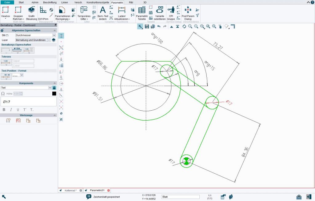
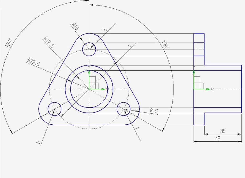
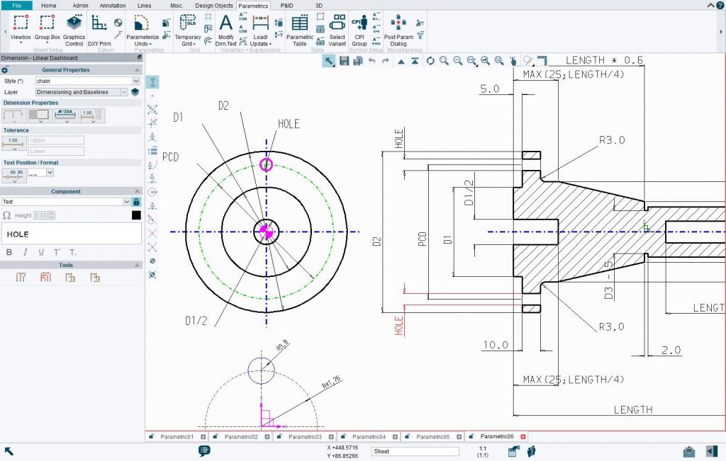
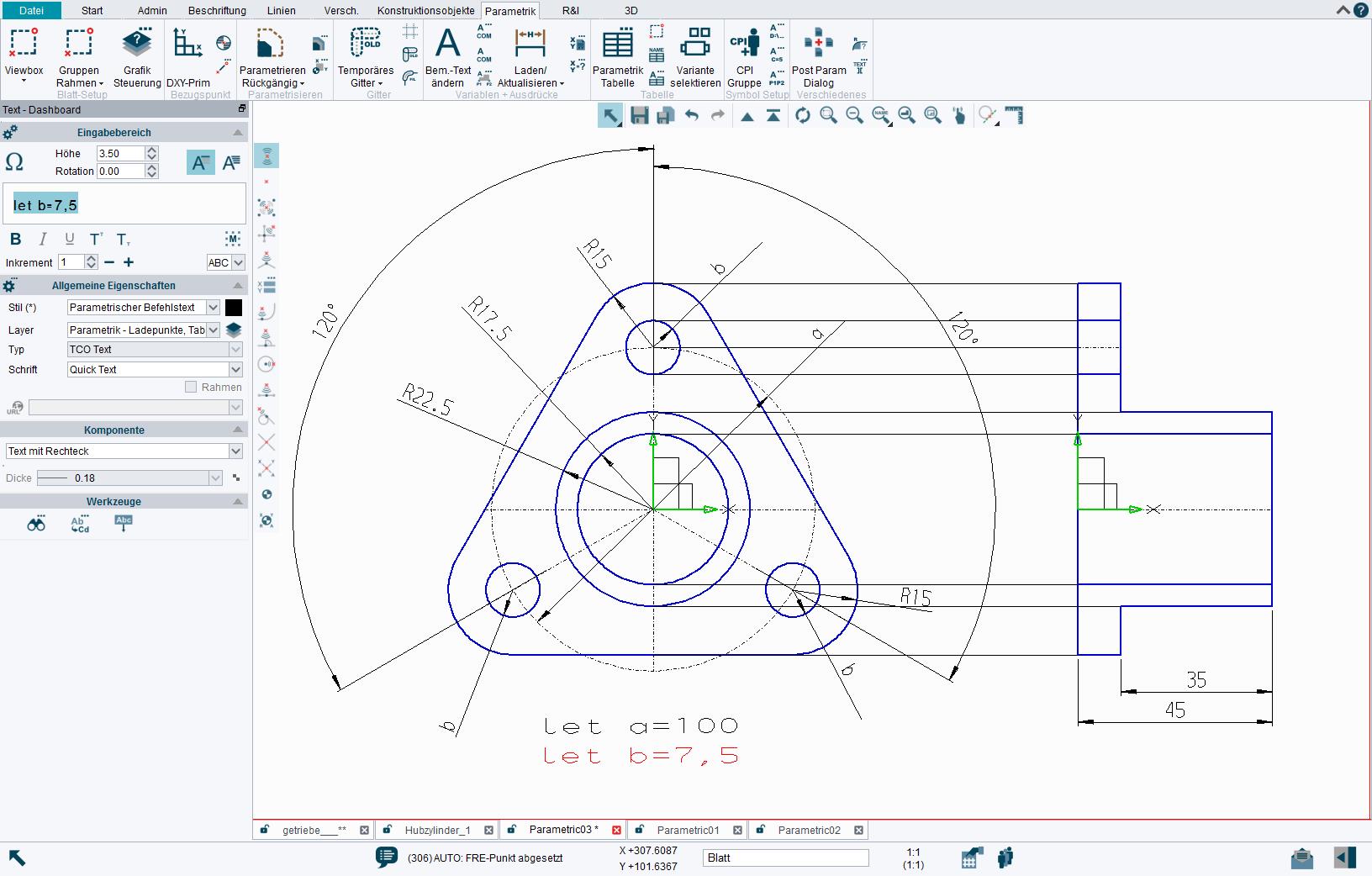
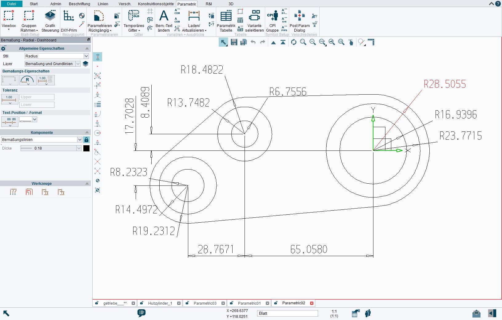
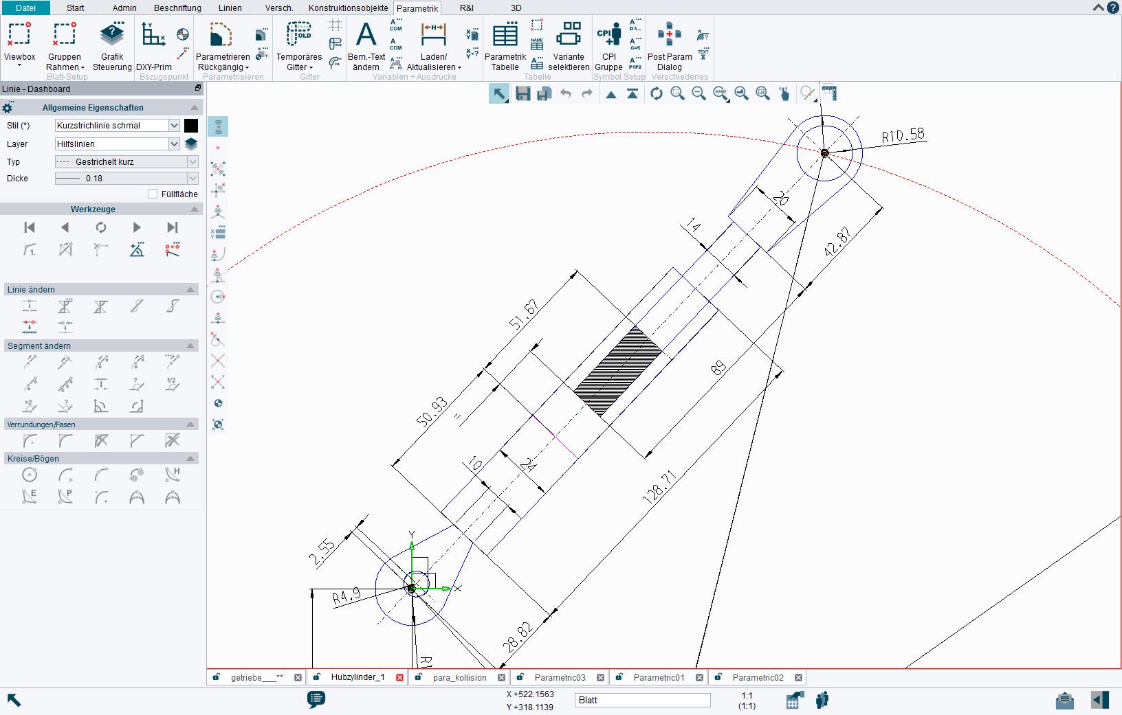
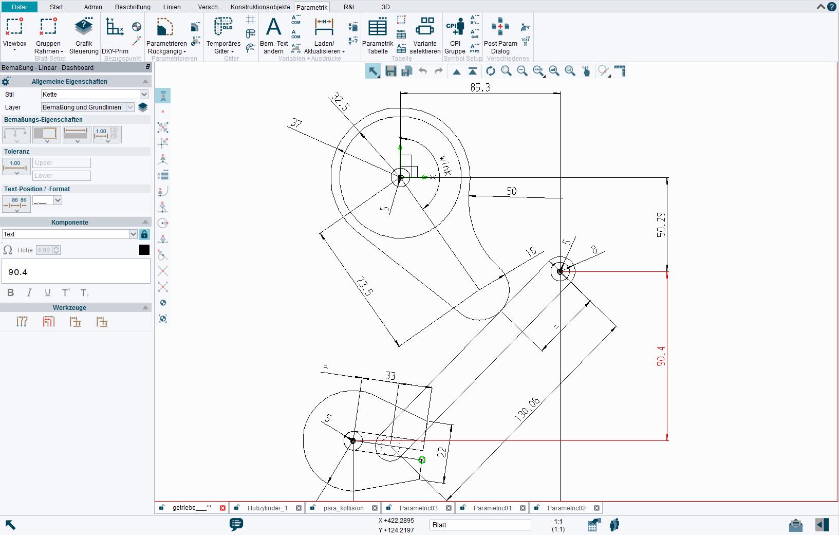
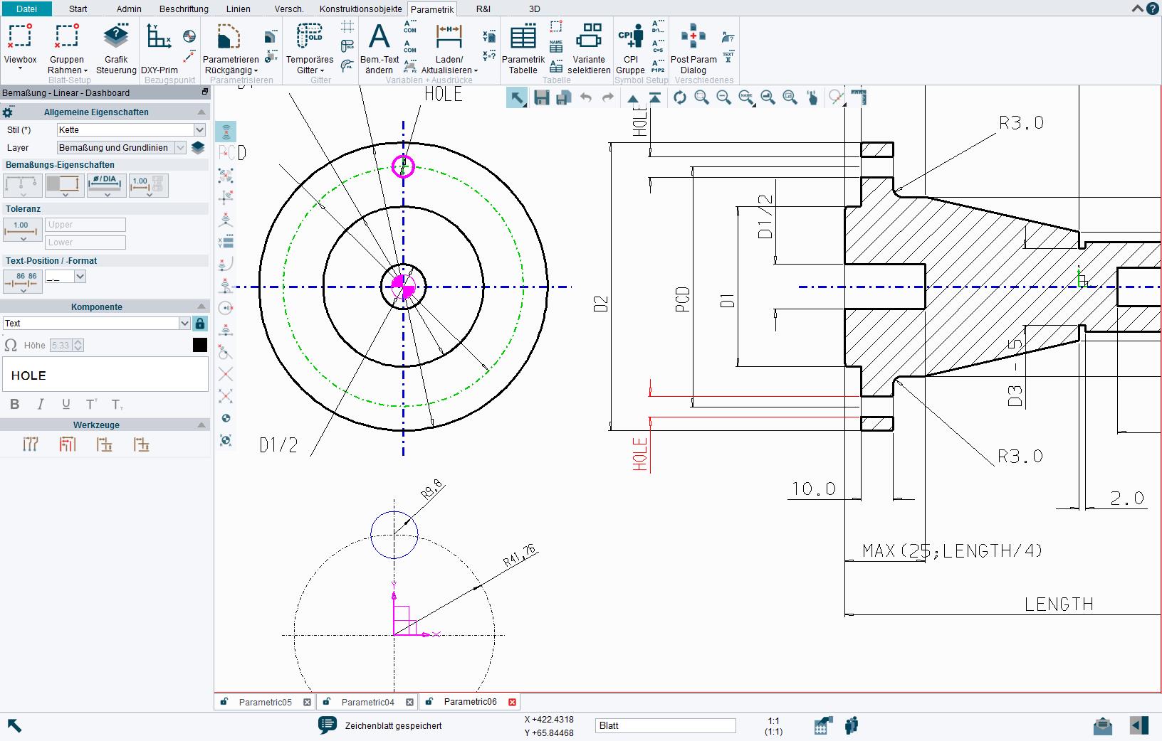
M4 DRAFTING’s familiar drafting tools allow you to easily create and dimension your geometry. Its parametric tool tray then provides access to all the additional functionality needed to parameterise your design. Use gridlines as a visual indicator of supported geometry, and a choice of static reference points to help set up your parameters. Group lines delineate areas of geometry that will not be parameterised (non-dimensioned points inside a group box do not have to be fully constrained), and you can define how those parts behave. Set up in-sheet parametric tables or command texts to create your variables, then save your parametric symbol or model files for use by other designers, who can be prompted to select or enter particular variables.
On loading, M4 DRAFTING automatically calculates and takes into account the geometric (tangential, angular, symmetric, collinear etc.) relationships between elements, meaning you can quickly create parts families, simulate 2D movements and displacement over time, check interferences, or validate design integrity. PARAMETRICS, often used in conjunction with M4’s Bacis1 and Bacis2 programming languages, are deployed on projects throughout the globe, ultimately providing fully automated creation of designs and production variants.
Don't miss M4 DRAFTING!
Try our 2D/3D CAD software now for free