How to layout your machinery installations in 3D
The responsibilities of a mechanical engineer are wide-ranging, and go far beyond the design of machinery. In many cases, engineers need to integrate new technologies into an existing plant or factory.
Large Layouts Cannot be Created Using Regular 3D CAD
The design of individual machines and conveyor units in 3D has become commonplace, and is now performed by nearly every supplier using 3D CAD software (e.g. Creo Parametric by PTC). These programmes focus on the detailed design of machines and their component parts, right down to the last screw. Unfortunately, this quickly creates a huge amount of model data, which is impractical to work with when it comes to laying out an entire production line or factory using a regular 3D CAD system. Consequently, the layout stage is often still performed in 2D.


A 3D Factory Layout System is the Solution
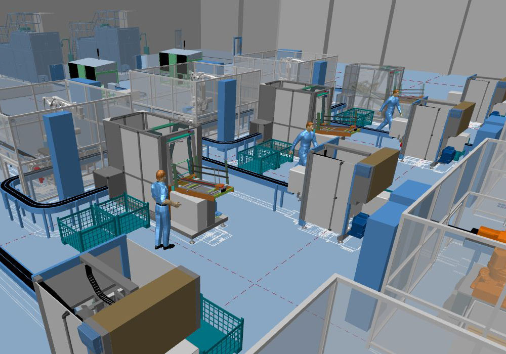
The latest high-performance 3D Factory Layout systems are purpose-built to handle large assemblies, and now offer the option of importing machinery models from 3D CAD directly into the overall layout. Using Factory Layout software Engineers can choose to layout their design in 2D or in 3D, but whichever method is used, the end result is always a 3D layout, with all the associated benefits of 3D.
Supports Familiar Working Methods

Which System is Best for 3D Machinery Layout
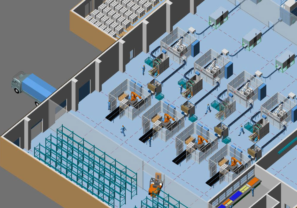
One system that combines factory layout with mechanical handling is M4 PLANT. Its Factory Layout and Mechanical Handling modules include all the functionality needed to quickly design large production lines, and even whole factories, in 3D. Furthermore, accurate parts lists and detailed 2D construction drawings can be automatically generated directly from the finished 3D design.
The fact is that a 3D layout system can be used to create high-performance 3D planning for very large factories or production lines, including all the necessary 2D derivations.

