Process engineering: Complete overview with examples and tips

Process engineering is one of the four major disciplines of engineering science and deals with the technical processes involved in the conversion of materials and energy into products on an industrial scale. Process engineering is of enormous economic importance and the designer needs tools to facilitate the tasks involved in process engineering design.

Process engineering – what is it?

Process engineering stands between the raw material and the finished product. It is used to describe all processes in which a product is created from a raw material. With the help of process engineering, the composition, properties or physical state of raw material are transformed to create the finished product. Process engineering is involved in the production of food, medicines, clothing, materials and building materials. In other words, process engineering stands between the raw material and the finished end product.

The processes in process engineering

Process engineering refers to the processes involved in creating a product from raw material. These material change processes are also known as procedures. During the manufacture of a product, multiple processes may be used to transform the raw material.

Process engineering is divided into three main categories:

  • Mechanical
  • Thermal
  • Chemical

Thermal processes are usually more energy-intensive than the mechanical processes, as large amounts of energy or heat are consumed by them. A wide variety of processes, both large and small, take place in a typical process plant and its associated equipment.

Unit operations in process engineering

In order to have a clear understanding of processes, they are divided into so-called unit operations, each of which involves a physical change or chemical transformation. The overall process is only finished when the various unit operations , such as mixing, stirring, sedimentation, filtration, evaporation, etc., have been performed in sequence.

Process engineering in plant design

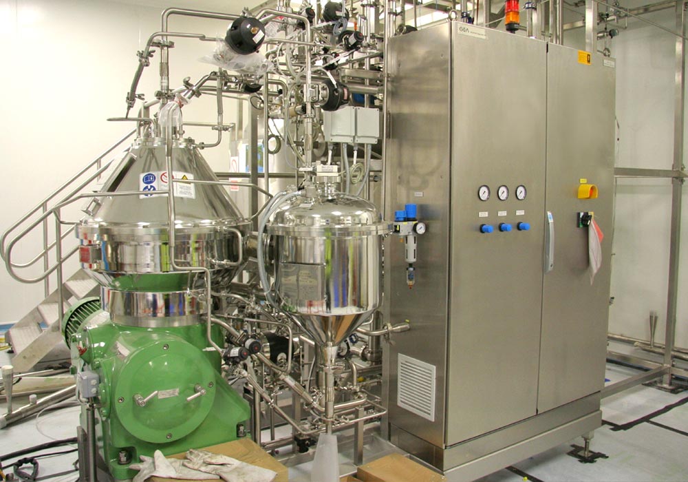
The realisation of a plant that has been designed using process engineering is called plant design. A plant contains the various equipment, machinery and other devices needed to perform a process. The transformation of material takes place in the equipment. Process engineering concentrates on the processes that occur in the equipment and documents them using computational methods.

Today, increasingly user-friendly software packages are used to solve complex tasks. This applies in particular to the optimisation of processes and documentation. Even faster process engineering design requires modern software that supports and optimises the design process.

Pipework for transportation

The transportation of materials around a plant is often achieved using pipes and conveyors. The chosen means of transportation depends on the material to be moved. Therefore, a distinction is made between the transportation of solids, liquids and gases. The goals of transportation are to move materials safely, gently, quickly and cost-effectively over the shortest possible distance between the units.

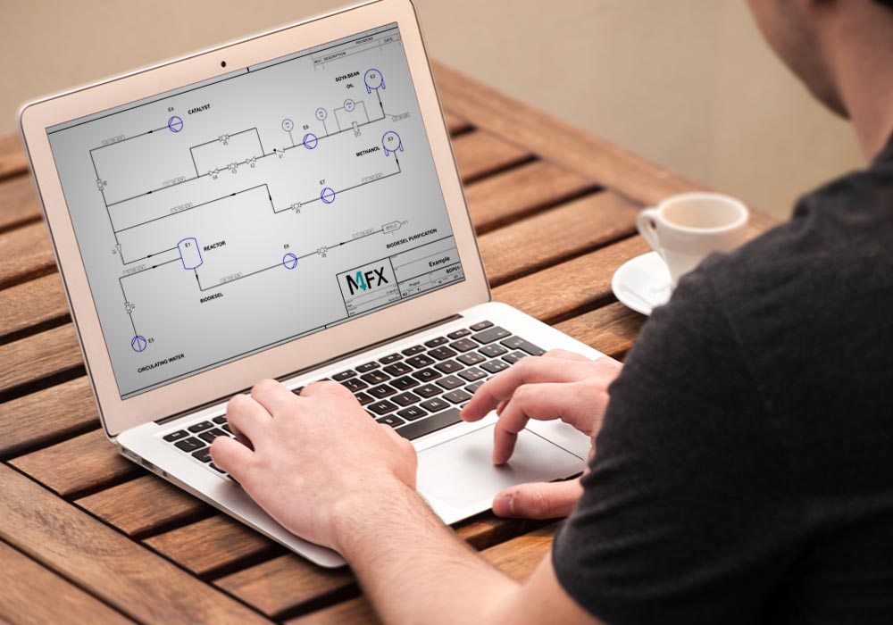
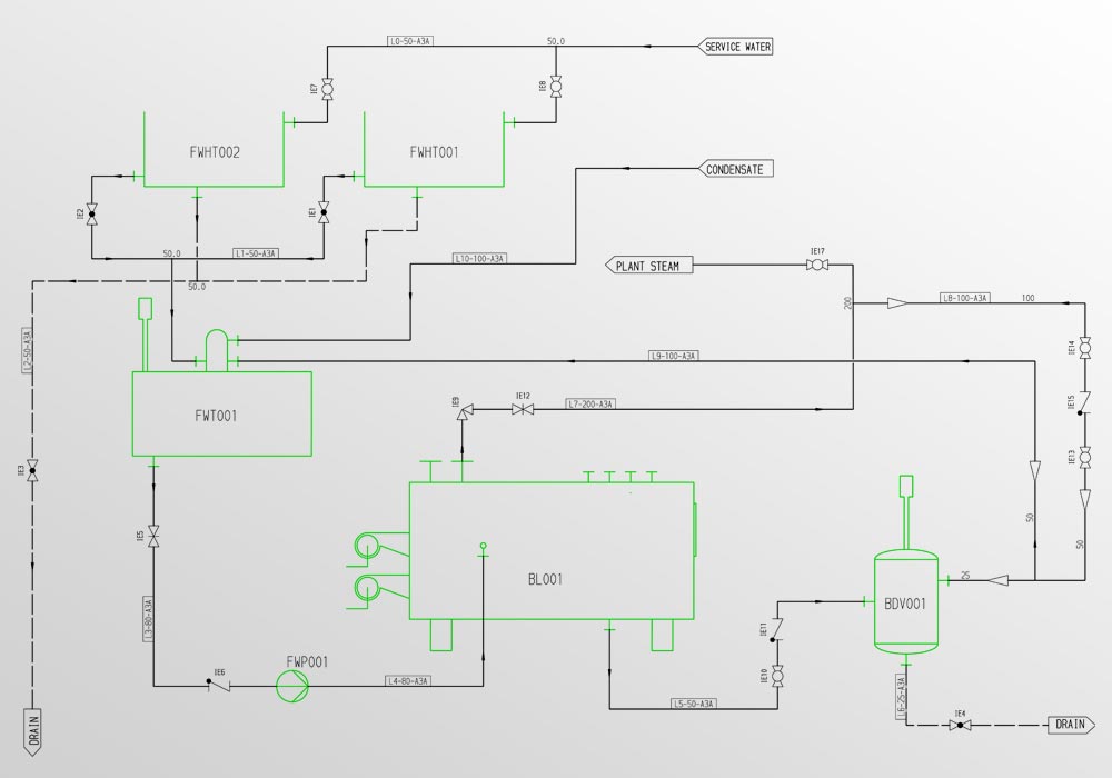
One of the most important means of transportation in process engineering is pipework. Networks of pipes connect individual pieces of equipment to form a system. The pipes supply sources of energy and raw materials. In process engineering, all pipework , equipment and machinery are represented schematically by graphic symbols on a so-called Piping & Instrumentation Diagram (P&ID).

Challenges in process engineering

A key step in the design process is the documentation of the design using a Piping & Instrumentation diagram (P&ID). All of the main system components are represented by symbols on the diagram. The symbols are logically connected by lines, which mostly represent pipes. The diagrams also include symbols for instrumentation for measurement and control. A P&ID can be visually created using any graphical 2D software package, but as the saying goes, the devil is in the detail, and this cannot be conveyed using simple graphics alone.

Realization of a process plant

The Piping & Instrumentation diagram graphically illustrates the design using symbols and lines. It also illustrates component relationships that are fundamental to the design. Therefore, the properties of each system component must be precisely specified so that the plant can be constructed as designed. With graphics-only design systems, the properties of each component must be manually defined in separate documents. That approach is very labour intensive, cumbersome and error prone.

Lean processes create time to do more

All companies look for ways to reduce time and thus costs, and often focus on company processes, because the shortening or automation of individual processes creates room to manoeuvre. Time saved translates into more time to undertake more projects with the same team. A popular solution is to deploy software that improves and, where possible, automates manual tasks and processes.

The right software for process engineering design

Modern software supports process engineering design by adding intelligence to Piping & Instrumentation diagrams. This means that the properties of individual components need to be entered only once when placing component symbols. Thereafter, all reports and parts lists can be generated automatically from the diagram of the process engineering design. A modern P&ID software package completely eliminates the need to manually create external documents, thereby saving time and avoiding the risk of human error.

Higher quality process engineering designs

In addition to the creation of design documentation, modern software solutions offer advanced functionality that is specifically aimed at ensuring high quality process engineering design. For example, the software checks that all components have been correctly named and that the required component properties have all been specified. Consistency checks also ensure that design errors are detected and reported early on. This advanced functionality requires no further time from the designer because it is performed automatically by the software.

Invest today, profit tomorrow

Process engineering design software that supports these features does not necessarily have to be expensive. For an investment of just a few hundred euros you can equip your team with modern Piping & Instrumentation diagramming software. Often video tutorials and complete user manuals are available, with which users can quickly learn the software. Due to the high quality of designs produced, and the automation of key design tasks, a rapid return on investment (ROI) is often achieved over the course of the very first project.

Download software for process engineering today

One of the key software vendors in this field is CAD Schroer. With its M4 P&ID FX software it provides a comprehensive solution for process engineering design. In addition to extensive P&ID diagramming functionality, the software is supplied with a range of standards-compliant symbol catalogues, and features consistency checking and automatic BOM generation. The software also contains 2D drafting functionality enabling you to further annotate your designs if you wish. Extensive interfaces to other systems ensure uncomplicated data exchange with your customers and suppliers. A downloadable trial version and detailed video tutorials are available, so that you can quickly evaluate and deploy the software in-house. Intelligent software for process engineering enables you to master your design challenges. For an investment of just a few thousand euros you can equip your team with modern P&ID software.

Overview of M4 P&ID FX – Software for process engineering design

Today, process engineering design requires modern software that supports and optimizes the design process

Process engineering designers are increasingly subject to challenging time pressures. Even preparing a proposal requires detailed design work to be performed as quickly as possible and to a very high standard. Intelligent software for process engineering meets these demands.

FAQ – Frequently asked questions about process engineering

The process diagram represents the transfer processes between flowing media in the form of symbols and lines. It also illustrates all the technical interrelationships that are necessary for practical processing. In order for the system to function optimally later on, the properties of each individual component must also be precisely defined when planning the system.
Process engineering has many tasks and one of them is the documentation of the planning in a process diagram. In this, all components required in the plant are recorded as symbols on a drawing. These are logically connected by lines, which usually stand for pipelines. A process diagram contains all symbols of the instruments that are needed for the processes in the plant for measurement or control.
Modern P&ID software supports process engineering design by making the documentation created in the form of P&ID diagrams evaluable. In doing so, the design team simply enters the properties for the individual components directly in the placement of the symbols and the lines when creating the process diagram. Afterwards, all information in the form of different reports or parts lists can be easily derived from the process engineering design. The manual creation of individual documents is completely eliminated. Errors are also reduced, as the software always creates the documents on the basis of the most up-to-date design.
Special software solutions for process engineering come with functions that guarantee a high quality of process engineering design. For example, these systems check whether numbering has been carried out properly or whether all details have been entered for the design. Consistency checks additionally ensure that potential errors are detected at an early stage and made available to the team in the form of a report. All this does not require any additional time, but is carried out quite automatically by the software.
Process engineering software that covers all the requirements for process engineering design does not necessarily have to be expensive. Already with an investment starting at 79 euros per month, you can equip your team with several licences of a modern P&ID software. With the help of a free trial version and detailed video tutorials, the software can be quickly tested and introduced in the company.
Scroll to Top