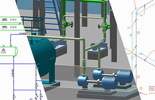
P&IDs, 3D Pipework and Piping Isometrics in One Integrated System
The design of process plant and pipework requires the creation of P&IDs, the design of process equipment and pipe systems, and the production of the associated piping isometric drawings.
Many manual steps when designing pipework
Process plant design begins with the creation of a schematic piping and instrumentation diagram (P&ID) to define the overall process. This is followed by the creation of a pipework layout that shows the position of the process equipment and the interconnected pipework, steelwork and other necessary components. Lastly, piping isometric drawings are generated for the pipework. These drawings detail each pipe spool ready for manufacture and assembly.

When the above tasks are undertaken using traditional drafting methods, or even with specialised, but separate, unintegrated software packages, this results in poor re-use of information between the design stages. This leads to the duplication of design data input at each stage, and therefore many opportunities for human error to creep in. This in turn leads to lengthy design times, poor overall design quality and inevitably, downstream construction problems and delays.
For example, with many P&ID drafting packages the resulting P&IDs often contain simple graphics with little or no detailed information about the actual components to be used. Even when intelligent P&IDs can be produced, the lack of integration between the packages means that much of the design data has to be input again during the pipework layout stage, and there is no way to check the consistency of the design data from P&ID to pipework layout. Furthermore, where piping isometrics are manually produced using a separate package, this again requires further duplication of data and gives scope for problems to arise.

Invest or be overtaken
That’s why you should use modern pipework design software
The latest pipework design systems provide new functionality that completely automates design tasks that were previously manually performed. They also offer pre-defined part catalogues and specialised layout tools that speed up the design process. And the best thing about today’s leading systems, such as M4 PLANT, is that they are highly affordable.

Using existing design data
Fully integrated and automated
M4 PLANT provides an integrated suite of intelligent software that enables design information to flow from the P&ID to 3D pipework layout and onto the production of piping isometric drawings. This avoids the duplication of data input, thus eliminating opportunities for human error and speeding up the overall design process.
M4 PLANT also offers comprehensive standards-based symbol libraries and parametric part catalogues, which further greatly speed the design process. This is complemented by M4 PLANT’s auto-routing capability that enables designers to quickly explore and finalise pipework routes.

Modernise your pipework design now
The use of a modern pipework design system such as M4 PLANT offers huge potential for savings. Design work can be performed faster and more effectively than before, and expensive tasks, such as the manual drafting of piping isometrics, are completely eliminated. Thanks to M4 PLANT’s interference and consistency checking systems, design errors can be easily detected and resolved, thereby avoiding costly on-site construction issues and project delays. It soon becomes clear that M4 PLANT will pay for itself after just a few projects, enabling even the most investment-cautious companies to get into the fast lane.

Need Support during the test phaseof M4 PLANT?
FAQs
Yes, the integration of P&ID with 3D piping design makes a lot of sense, as it creates a consistent database. The direct transfer of the data defined in P&ID to the 3D design avoids information losses and increases the accuracy of the design.
Integration can be achieved using software solutions that support design in both P&ID and 3D. These systems use standardised data formats and interfaces to ensure a seamless flow of information between the design phases. Data conversion tools and protocols transfer all relevant information without manual intervention.
The automatic generation of piping design from P&ID data is carried out by specialised software that interprets the components and their relationships defined in the P&ID and converts them into a 3D model. This software often uses advanced algorithms for routing and placement of components to meet real-world requirements and speed up the design process. One software that supports this process is M4 PLANT.
Yes, modern design software can automatically generate piping isometrics from 3D piping design. Systems such as M4 PLANT directly extract relevant information such as dimensions, materials and connection details from the 3D model and create detailed isometric drawings for production and assembly.
M4 PLANT is software that seamlessly integrates P&ID, 3D piping design, and the automatic creation of piping isometrics. This software allows for the uniting of the entire design process under one roof, which increases efficiency, reduces design effort, and ensures high-quality design results.