[vc_row][vc_column width=”1/2″][vc_column_text]
Saving 3D Views for Collaborators and Customers
In addition to the existing tools for choosing different views and conducting camera-like 3D walk-throughs, MPDS4 REVIEW now allows users to name and store different views of a model or plant, which can then be selected and displayed at any time.
This makes the tool even more ideal for collaboration with suppliers, colleagues and customers, as different views can be saved with a model, which can quickly be selected during a presentation to (or by) a customer, or during a meeting with collaborators.
MPDS4 REVIEW version 1.2 is available for immediate download for CAD Schroer maintenance customers via its Customer Portal.
![]() Log in to the CAD Schroer Customer Portal[/vc_column_text][/vc_column][vc_column width=”1/2″][vc_column_text]
Log in to the CAD Schroer Customer Portal[/vc_column_text][/vc_column][vc_column width=”1/2″][vc_column_text]
Gaining a Structural Overview
In addition to showing details and attributes for selected components within a plant or factory, version 1.2 now allows users to gain an overview of the structure of the 3D data by providing a structure tree, which lists systems, subsystems, and individual components.
Measuring Distances
Version 1.2 now also allows users to measure distances between components, and to display these distances on the screen. The model can be saved with distances displayed.[/vc_column_text][/vc_column][vc_row][vc_column width=”1/2″][vc_column_text]
About MPDS4 REVIEW
MPDS4 REVIEW is an external 3D review and feedback tool. The software is used to interactively review MEDUSA4 3D CAD data in detail, or to walk through an entire industrial plant, generated by CAD Schroer’s MPDS4 plant design system. The system enables users to see model properties and attach comments for designers, which are saved with the model.
 MPDS4 REVIEW Web Page and Datasheet
[/vc_column_text][/vc_column][vc_column width=”1/2″][vc_column_text]
2D to 3D Made Easy
Your design process is ideally suited to 2D, but occasionally you have a need for 3D? MEDUSA4 3D provides the perfect answer!
Do you find yourself needing to:
- Design or visualise a particularly complex part
- Exchange 3D data with customers and suppliers
- Do mass properties calculations
- Carry out FE analysis?
Then MEDUSA4 3D offers the following benefits:
- Use 3D when and where appropriate, without having to bear the cost and time overheads associated with a full 3D approach.
- Retain full compatibility with your 2D design data and process.
- Use simple and easy modelling techniques based on orthographic projection, familiar to all designers.
- Produce drawings automatically from 3D models. This speeds up drawing production when modelling is used. The drawings can be used with the rest of your 2D process drawings, e.g. assembly, installation, manufacturing and tooling drawings.
- Use existing 2D drawings as the basis for 3D models – great where a model is needed purely for to meet a supplier or customer’s requirements.
- Parameterise 3D designs using MEDUSA4 PARAMETRICS
- Do quick mass properties calculations on your model
- Easily exchange data with other 3D systems, and create output for Finite Element Analysis
- MEDUSA4 basic 3D is included in all MEDUSA4 ADVANCED packages. MEDUSA4 3D PLUS is available as an add-on module.
[/vc_column_text][/vc_column][vc_row][vc_column width=”1/2″][vc_column_text]
MEDRaster Colour
The new colour raster module allows customers to incorporate full colour images and scanned drawings into their designs. Around 90 major image formats are now supported. Existing customers with the bitonal MEDRaster product can upgrade for a small fee. Both products now support up to 5 separate rasters in a design, with the option of saving them to file (associated with the sheet) or directly in the sheet.
Typical applications include :
- Addition of a colour-shaded view of a 3D model, to supplement a dimensioned drawing. (Unlike other systems, MEDRaster Colour allows you to store the image within the sheet)
- Insertion and management of scanned paper designs – monochrome or colour – to avoid unnecessary rework
- Incorporation of maps or other colour-coded diagrams as supplementary design information
- Insertion of colour graphs and other images from non-CAD software for illustration or sales and marketing purposes
- Provision of graphical instructions or photographs for downstream applications
- Incorporation of graphical analysis or property data (such as visual stress analysis or heat transfer data) of design components for manufacturers or end customers
[/vc_column_text][/vc_column][vc_column width=”1/2″][vc_column_text]
MPDS4 FACTORY LAYOUT
The pioneering new 2D to 3D application for installation designers was conceived specifically for mechanical machinery vendors who sell complete installations. MPDS4 FACTORY LAYOUT offers virtually unique 2D to 3D functionality for quick and easy installation layout and space management, making sophisticated 3D project proposals possible – and affordable – even in the early tender stage.
Do you
- Design and deliver capital plants, factories or other installations for discerning clients?
- Need to quickly provide winning project proposals?
- Want to combine the quick and effective layout capabilities of a 2D system with the detailed space management and visualisation side of a 3D tool, with minimum use of time and resources?
Then it’s time you had a closer look at MPDS4 FACTORY LAYOUT, the ultimate in 2D/3D interaction for rapid installation design.
[/vc_column_text][/vc_column][vc_row][vc_column width=”1/2″][vc_column_text]
Text handling and DXF/DWG Conversion
Unicode provides a universal architecture and encoding for all languages of the world, with nearly 100,000 characters currently encoded. This means more multi-language support for MEDUSA4, and even better integration with other systems.
With Unicode you can now:
- Use any scaleable operating system font on all supported platforms
- Cut and paste text from your Web browser to the MEDUSA text tool
- Use the Text Translator with any installed language
- Exchange data with other systems
The CADConvert interface for DXF/DWG conversion now:
- Reads and writes AutoCAD® DWG 2007
- Reads and writes Unicode (the most common AutoCAD ANSI code pages)
- Imports AutoCAD layer names
- Exports group names as block names
- Imports splines (NURBS) as curves
[/vc_column_text][/vc_column][vc_column width=”1/2″][vc_column_text]
MPDS4 MECHANICAL HANDLING™
 A New Discipline for Intelligence in Interconnected Components: Introducing the ideal companion for MPDS4 FACTORY LAYOUT (the module for fast 2D conceptual design and easy 3D visualisation of large installations): MPDS4 MECHANICAL HANDLING is a new discipline for placing intelligent interconnected components. From conveyor belts to cranes to fork lift trucks, installation designers can now easily select, lay out, configure, visualise and add intelligence to process machinery in their plant.
Custom Schematic Symbol Libraries
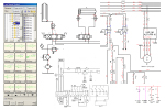 Do you regularly create hydraulic, pneumatic or electric schematics, but spend a lot of time adapting standard symbols or creating new ones from scratch? Then its time to speak to one of our engineers. We can create customised symbol libraries or easily adaptable templates for your company, immediately cutting design time and costs while improving design quality, consistency and company flexibility and responsiveness. [/vc_column_text][/vc_column][vc_row][vc_column width=”1/2″][vc_column_text]
MPDS4 MECHANICAL HANDLING™
 A New Discipline for Intelligence in Interconnected Components: Introducing the ideal companion for MPDS4 FACTORY LAYOUT (the module for fast 2D conceptual design and easy 3D visualisation of large installations): MPDS4 MECHANICAL HANDLING is a new discipline for placing intelligent interconnected components. From conveyor belts to cranes to fork lift trucks, installation designers can now easily select, lay out, configure, visualise and add intelligence to process machinery in their plant.
Custom Schematic Symbol Libraries
 Do you regularly create hydraulic, pneumatic or electric schematics, but spend a lot of time adapting standard symbols or creating new ones from scratch? Then its time to speak to one of our engineers. We can create customised symbol libraries or easily adaptable templates for your company, immediately cutting design time and costs while improving design quality, consistency and company flexibility and responsiveness. [/vc_column_text][/vc_column][vc_column width=”1/2″][vc_column_text]
MPDS4 REVIEW: Easy Model Review by Clients
 The new MPDS4 REVIEW tool provides an easy way to share models and communicate with customers and suppliers who do not have MPDS4 installed. It allows users to easily interact with your MEDUSA4 3D or MPDS4 models, conducting plant and scenery walk-throughs or inspecting designs in detail. Models are delivered by MPDS4 in a very compact format for fast viewing, and can be e-mailed to clients for daily design reviews or taken on-site by Project Managers to be viewed on any machine.
[/vc_column_text][/vc_column][vc_row][vc_column width=”1/2″][vc_column_text]
MPDS4 REVIEW: Easy Model Review by Clients
 The new MPDS4 REVIEW tool provides an easy way to share models and communicate with customers and suppliers who do not have MPDS4 installed. It allows users to easily interact with your MEDUSA4 3D or MPDS4 models, conducting plant and scenery walk-throughs or inspecting designs in detail. Models are delivered by MPDS4 in a very compact format for fast viewing, and can be e-mailed to clients for daily design reviews or taken on-site by Project Managers to be viewed on any machine.
[/vc_column_text][/vc_column][vc_column width=”1/2″][vc_column_text]
The new version of CAD Schroer’s external 3D review tool for MPDS4 and MEDUSA4 data makes it even easier for industrial designers to communicate ideas and changes to project stakeholders and customers
CAD Schroer has announced the release of version 1.2 of MPDS4 REVIEW. The latest version includes new structure information, measuring and 3D view options.[/vc_column_text][/vc_column][vc_row][vc_column width=”1/2″][vc_column_text]
Smart Drafting Tool: The new way to create geometry
The new smart drafting facility in STHENO/PRO ADVANCED™ provides the means to quickly and easily generate geometry without the need for construction lines prior to drawing. The Smart Drafting Tool allows construction lines to be automatically inferred between points created and displays them dynamically as the cursor moves inside the drawing area.[/vc_column_text][/vc_column][vc_column width=”1/2″][vc_column_text] [/vc_column_text][/vc_column][vc_row][vc_column width=”1/2″][vc_column_text]
Project Data Control (PDC)
Project Data Control (PDC) ist eine optionale in MEDUSA4 und MPDS4 integrierte Datenmanagement Lösung für Konstruktionsdaten und die damit verwendeten Dokumente. Durch die offene Architektur bietet PDC vielseitige Integrationsmöglichkeiten. Dadurch können die Daten sowohl für andere PLM-, PDM- und ERP-Systeme zur Verfügung gestellt oder gar über das Web für andere Nutzergruppen zugänglich gemacht werden.
PDC erlaubt die Generierung einer an die Kundenanforderungen angepassten Datenbankstruktur, wobei entweder eine Oracle- oder andere Datenbank-Architektur verwendet werden kann. Der Zugriff auf die Datenbank erfolgt dabei aus MPDS4, MEDUSA4 oder dem Web. PDC erlaubt dabei die Verwaltung von allen konstruktionsnahen Daten, wie 3D-Modellen (DXF, STL, IGES, STEP, VRML, MOD), 2D-Zeichnungen, Tabellen oder Rohrleitungsisometrien. Natürlich werden auch alle zum Dokument dazugehörigen Daten, wie benutzerspezifische Attribute, Verweise, Stücklisten oder aktueller Bearbeitungsstatus vom System mit verwaltet.
PDC ermöglicht die Zusammenarbeit zwischen weltweit verteilten Teams, mit einer einfachen Implementierung und Administration. Die Vernetzung verschiedener Standorte erlaubt einen kontrollierten Datenaustausch bis hin zur kompletten Synchronisation gesamter Projektdatenbanken.[/vc_column_text][/vc_column][vc_column width=”1/2″][vc_column_text]
Project Data Control (PDC)
Project Data Control (PDC) ist eine optionale in MEDUSA4 und MPDS4 integrierte Datenmanagement Lösung für Konstruktionsdaten und die damit verwendeten Dokumente. Durch die offene Architektur bietet PDC vielseitige Integrationsmöglichkeiten. Dadurch können die Daten sowohl für andere PLM-, PDM- und ERP-Systeme zur Verfügung gestellt oder gar über das Web für andere Nutzergruppen zugänglich gemacht werden.
PDC erlaubt die Generierung einer an die Kundenanforderungen angepassten Datenbankstruktur, wobei entweder eine Oracle- oder andere Datenbank-Architektur verwendet werden kann. Der Zugriff auf die Datenbank erfolgt dabei aus MPDS4, MEDUSA4 oder dem Web. PDC erlaubt dabei die Verwaltung von allen konstruktionsnahen Daten, wie 3D-Modellen (DXF, STL, IGES, STEP, VRML, MOD), 2D-Zeichnungen, Tabellen oder Rohrleitungsisometrien. Natürlich werden auch alle zum Dokument dazugehörigen Daten, wie benutzerspezifische Attribute, Verweise, Stücklisten oder aktueller Bearbeitungsstatus vom System mit verwaltet.
PDC ermöglicht die Zusammenarbeit zwischen weltweit verteilten Teams, mit einer einfachen Implementierung und Administration. Die Vernetzung verschiedener Standorte erlaubt einen kontrollierten Datenaustausch bis hin zur kompletten Synchronisation gesamter Projektdatenbanken.[/vc_column_text][/vc_column][vc_row][vc_column width=”1/2″][vc_column_text][Translate to English:] [/vc_column_text][/vc_column][vc_column width=”1/2″][vc_column_text][Translate to English:] [/vc_column_text][/vc_column][vc_row][vc_column width=”1/2″][vc_column_text]
Optimiertes Handling von 2D Zeichnungen
In MEDUSA4 Version 5.1.2 wurden Verbesserungen bei den 2D Zeichenwerkzeugen und Hilfslinien vorgenommen. Das Handling sehr großer Zeichnungsblätter wurde optimiert. Genauso wurde die Verwaltung von Layern auf einem Blatt verbessert.[/vc_column_text][/vc_column][vc_column width=”1/2″][vc_column_text]
Optimiertes Handling von 2D Zeichnungen
In MEDUSA4 Version 5.1.2 wurden Verbesserungen bei den 2D Zeichenwerkzeugen und Hilfslinien vorgenommen. Das Handling sehr großer Zeichnungsblätter wurde optimiert. Genauso wurde die Verwaltung von Layern auf einem Blatt verbessert.[/vc_column_text][/vc_column][vc_row][vc_column width=”1/2″][vc_column_text]
CADConvert DXF/DWG (AutoCAD®) Schnittstellen-Erweiterung
Ab Version 5.1 unterstützt die CADConvert Schnittstelle das DXF/DWG-Format von AutoCAD R12 bis AutoCAD 2012.
In MEDUSA4 Version 5.1.2 wurden Verbesserungen an der DXF/DWG-Schnittstelle CADConvert vorgenommen, die eine verbesserte Handhabung von Sonderzeichen und Bögen beinhaltet. Weiterhin wurden die Positionierung von Textelementen und die Nutzung sehr kleiner oder sehr großer Skalierungen verbessert.[/vc_column_text][/vc_column][vc_column width=”1/2″][vc_column_text]
CADConvert DXF/DWG (AutoCAD®) Schnittstellen-Erweiterung
Ab Version 5.1 unterstützt die CADConvert Schnittstelle das DXF/DWG-Format von AutoCAD R12 bis AutoCAD 2012.
In MEDUSA4 Version 5.1.2 wurden Verbesserungen an der DXF/DWG-Schnittstelle CADConvert vorgenommen, die eine verbesserte Handhabung von Sonderzeichen und Bögen beinhaltet. Weiterhin wurden die Positionierung von Textelementen und die Nutzung sehr kleiner oder sehr großer Skalierungen verbessert.[/vc_column_text][/vc_column][vc_row][vc_column width=”1/2″][vc_column_text]
Neue Füllfunktion für geschlossene Geometrien
Ab der neuen MEDUSA4 Version 5.1 kann durch eine Füllfunktion eine geschlossene Geometrie entsprechend Ihrer Linienfarbe ausgefüllt werden. Diese neue grafische Funktion verbessert die Darstellung der technischen Daten und das allgemeine Handling von Flächen. Natürlich werden die gefüllten Flächen auch beim Import und Export zu DXF oder DWG mit übertragen.[/vc_column_text][/vc_column][vc_column width=”1/2″][vc_column_text]
Neue Füllfunktion für geschlossene Geometrien
Ab der neuen MEDUSA4 Version 5.1 kann durch eine Füllfunktion eine geschlossene Geometrie entsprechend Ihrer Linienfarbe ausgefüllt werden. Diese neue grafische Funktion verbessert die Darstellung der technischen Daten und das allgemeine Handling von Flächen. Natürlich werden die gefüllten Flächen auch beim Import und Export zu DXF oder DWG mit übertragen.[/vc_column_text][/vc_column][vc_row][vc_column width=”1/2″][vc_column_text]
MPDS4: iPhone® / iPod touch® App Puts a 3D Plant in Your Pocket
Viewing 3D plant designs no longer requires expert software. CAD Schroer’s MPDS4 PLANT DESIGN and factory layout software output and MWF Technology’s “On-Hand Viewer” iPhone / iPod touch app now make it easy for anyone to view 3D data on the go.
Find out more about the iPhone® App and MPDS4
Watch a demo video on YouTube [/vc_column_text][/vc_column][vc_column width=”1/2″][vc_column_text]
MPDS4: iPhone® / iPod touch® App Puts a 3D Plant in Your Pocket
Viewing 3D plant designs no longer requires expert software. CAD Schroer’s MPDS4 PLANT DESIGN and factory layout software output and MWF Technology’s “On-Hand Viewer” iPhone / iPod touch app now make it easy for anyone to view 3D data on the go.
Find out more about the iPhone® App and MPDS4
Watch a demo video on YouTube [/vc_column_text][/vc_column][vc_row][vc_column][vc_column_text] [/vc_column_text][/vc_column][/vc_row]
The “On-Hand Viewer” iPhone app allows MPDS4 users to review 3D data on the phone in their pocket
L’application “On-Hand Viewer” de l’iPhone permet aux utilisateurs MPDS4 de visualiser des données 3D sur leur téléphone portable
Il visualizzatore nelle “proprie mani”,L’applet per iPhone permette agli utenti MPDS4 di vedere i dati 3D dal telefono che hanno nelle loro tasche
MPDS4 Anlagen mit der iPhone und iPod touch Applikation On-Hand Viewer herunterladen und betrachten
The “On-Hand Viewer” iPhone app allows MPDS4 users to review 3D data on the phone in their pocket
L’application “On-Hand Viewer” de l’iPhone permet aux utilisateurs MPDS4 de visualiser des données 3D sur leur téléphone portable
Il visualizzatore nelle “proprie mani”,L’applet per iPhone permette agli utenti MPDS4 di vedere i dati 3D dal telefono che hanno nelle loro tasche
[vc_row][vc_column][vc_column_text] [/vc_column_text][/vc_column][/vc_row]
[vc_row][vc_column][vc_column_text] [/vc_column_text][/vc_column][/vc_row]
[vc_row][vc_column][vc_column_text] [/vc_column_text][/vc_column][/vc_row]
[vc_row][vc_column][vc_column_text] [/vc_column_text][/vc_column][/vc_row]
Das Smart Drafting Tool leitet automatisch Konstruktionslinien ab
The new Smart Drafting Tool automatically infers construction lines
[vc_row][vc_column][vc_column_text] [/vc_column_text][/vc_column][/vc_row]
Verschiedene 3D-Ansichten für den Kunden abspeichern
Unicode erleichtert die Erstellung mehrsprachiger Zeichnungen wie diese mit japanischem Zeichensatz
Unicode makes it easy to create multi-lingual drawings like this, using Japanese character sets
Unicode facilite la création de dessins multilingues tels que ceux-ci, en utilisant les jeux de caractères japonais
Con Unicode creare disegni multilingui come questi utilizzando caratteri giapponesi diventa semplicissimo
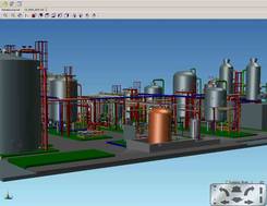
Konstruieren kompletter 3D-Fabrikanlagen direkt aus einem 2D-Layout
Build complete 3D plants directly from a 2D layout
Concevez un plan entièrement en 3D, à partir d’un shéma 2D
Realizzate impianti 3D completi direttamente a partire da disegni 2D
Editierbare Eigenschaften der eingebetteten Rasterdateien
Easily edit the properties of embedded raster files
Propriétés éditables des fichiers Raster intégrés
Elaborate in tutta praticità le proprietà di file raster integrati
Der MEDUSA4 3D-Modell-Viewer
The MEDUSA4 3D Model Viewer
MEDUSA4, visualiseur de modèles 3D
Il visualizzatore modello 3D di MEDUSA4
[vc_row][vc_column][vc_column_text] [/vc_column_text][/vc_column][/vc_row]
Abstände im Modell ausmessen und anzeigen
Modellstruktur und Komponenteninfos anzeigen
[vc_row][vc_column][vc_column_text] [/vc_column_text][/vc_column][/vc_row]
Store different 3D views for clients
[vc_row][vc_column][vc_column_text] [/vc_column_text][/vc_column][/vc_row]
Sauvegarder différentes vues 3D pour les clients
[vc_row][vc_column][vc_column_text] [/vc_column_text][/vc_column][/vc_row]
Salvataggio di diverse viste 3D per clienti
[vc_row][vc_column][vc_column_text] [/vc_column_text][/vc_column][/vc_row]
Measure & display distances in a model
[vc_row][vc_column][vc_column_text] [/vc_column_text][/vc_column][/vc_row]
Mesurer & afficher les distances dans un modèle
[vc_row][vc_column][vc_column_text] [/vc_column_text][/vc_column][/vc_row]
Misurare & mostrare dimensioni in un modello
View model structure & component info
Visualiser la structure du modèle & attributs du composant
[vc_row][vc_column][vc_column_text] [/vc_column_text][/vc_column][/vc_row]
Visualizzare strutture del modello & info sui componenti