Integrated piping design: Efficient from P&ID to 3D and isometrics

Rohrleitungsplanung

Pipeline design has evolved considerably in recent years. Whereas P&IDs, 3D models, and isometrics were once created separately, modern companies now rely on integrated piping design.

Contents
    Fügen Sie eine Überschrift hinzu, um mit der Erstellung des Inhaltsverzeichnisses zu beginnen

    Traditionally, piping design was carried out in several separate steps. P&IDs were created manually, often without direct interfaces to 3D design. All relevant data was then recorded in a separate table. Pipelines were then drawn in 2D or created using simple CAD programs. The piping isometrics, which were required for the production and documentation of the pipework, were created manually in another software program. These three separate steps were error-prone, as no common database existed.

    However, traditional methods are often time-consuming and error-prone. Digitalisation and modern software solutions make it possible to integrate these three steps seamlessly. Integrated design solutions that combine the creation of P&IDs, 3D modelling of pipelines, and pipeline isometrics for production can overcome these challenges and lead to optimised, forward-looking designs.
    Ganzheitliche Rohrleitungsplanung für alle Branchen

    From the idea to 3D system design: P&ID as a foundation

    Process engineering systems’ design usually begins with creating a P&ID (Piping and Instrumentation Diagram), which records all relevant apparatus, pipework, fittings and their logical relationships. This early recording of the process components forms the basis for the subsequent 3D piping design, where spatial considerations and construction details come into play. Thanks to a seamless flow of information between the P&ID and 3D system design, inconsistencies or potential conflicts can be recognised and resolved as early as the concept phase. This creates a continuous data thread, allowing any changes or additions to the P&ID to be immediately reflected in the spatial design.
    R&I Fließbild im Überblick

    Continuous data flow: from 3D design to automatic piping isometrics

    As soon as the 3D piping design has been completed, the piping isometrics can be generated automatically from the existing data. These isometrics are of central importance for production and assembly, as they contain detailed information such as welding points, lengths and parts lists. The great added value lies in that changes made in the P&ID or during 3D piping construction are directly visible in the production-ready isometric drawings without any manual intermediate steps. In this way, engineering and assembly teams benefit from a constantly up-to-date and consistent data basis. This lowers error rates, reduces rework and makes the entire design process more efficient – from the first line in the flow diagram to the final piping isometrics for production.
    R&I - Rohrleitungsbau - Rohrleitungsisometrien

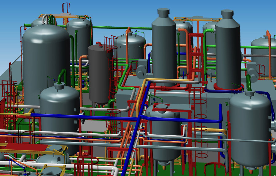
    The interaction of P&ID, 3D piping construction and piping isometrics

    An end-to-end design process that combines P&IDs, 3D piping design and piping isometrics creates maximum transparency and data consistency. As early as the process engineering phase, components are defined in the P&ID diagram, the information from which then flows into the 3D design. There, catalogues and auto-routing functions enable the previously created system components to be placed quickly and with minimal errors. The piping isometrics can then be generated fully automatically based on this consistent data – including welding points, exact lengths and all necessary parts lists and bending tables. This creates an integrated process chain in which the P&ID or 3D design changes can be immediately considered in the piping isometrics. This significantly reduces manual rework and potential sources of error.
    Software for integrated piping design
    With M4 PLANT, you can plan piping projects of any size. Create comprehensive P&ID plans, convert them into detailed 3D plans, and export all necessary documents, including piping isometrics.

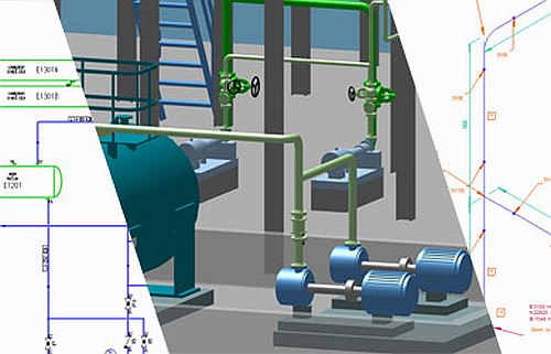
    The creation of parts lists in integrated design

    A central component of piping design is the parts list, which lists all the parts, materials and components required for a system.

    In traditional design processes, these lists were often created manually and maintained in separate tables, which was error-prone and time-consuming. Modern software solutions enable the automatic generation of parts lists directly from the 3D model or even from the P&ID data. Pipes, valves and other components are precisely recorded and brought together in a structured and consistent list. This automation not only saves time but also increases accuracy.


    One major advantage is the dynamic updating of parts lists: changes to the design, such as moving a valve or adjusting a pipe diameter, are automatically reflected in the parts list. This means that purchasing, production, and assembly always work with up-to-date data, the material flow is optimised, and errors in material logistics can be minimised. The integration of the parts list improves the efficiency of the entire piping design and contributes to the project’s cost-efficiency.

    Advantages of integrated piping design

    The combination of P&ID creation, 3D piping design and the creation of piping isometrics in one continuous process offers numerous advantages:

    1. Reduced design times

    By linking all design steps, changes can be implemented more quickly. For example, if parameters are changed in the P&ID diagram for certain components, these changes can be taken into account directly in the 3D design and the isometrics.

    2. Avoidance of design errors

    Incorrect piping design can cause considerable costs. By integrating the three steps, design errors can be recognised and rectified early.

    3. Automated creation of production documents

    Modern software solutions allow the automatic generation of:

    • Parts lists
    • Piping isometrics
    • Welding tables
    • Bending tables

    This automation saves time and ensures greater accuracy.

    4. Collision check in 3D design

    A key advantage of 3D modelling is the ability to check for collisions. This avoids subsequent problems on the construction site, which could otherwise result in high additional costs.

    5. Automatic quality inspection

    When creating P&ID data, for example, the automatic quality check ensures it is created entirely and consistently. In 3D design, only those components that fit together are used. Specifying which components or suppliers may be used at this stage is also possible.

    Automated data flows and increased efficiency

    Engineers and companies benefit in several ways thanks to the seamless link between P&ID, 3D piping design and isometrics. On the one hand, the shared database ensures automatic quality assurance: if, for example, a component is changed in the P&ID design, this information flows directly into the 3D model and ultimately appears correctly in the piping isometrics. In addition, it eliminates many manual work steps, such as when creating parts lists or production documents, which significantly shortens project lead times and reduces costs. Last but not least, the integrated approach creates a high level of design reliability, as everyone involved has access to the same level of information and can, therefore, work together smoothly. This efficient interaction positively affects all phases of the system life cycle – from the initial concept idea to subsequent maintenance and expansion.

    Challenges of collaboration between different

    Several teams are involved in piping design – from process engineers and designers to production and maintenance teams. One of the biggest challenges is that these teams often work in different software environments with different specialisms. Misunderstandings, inconsistencies, and time-consuming coordination can occur without a centralised data source. Changes to one part of the design often have to be manually updated elsewhere, which increases the risk of errors. An integrated design solution facilitates collaboration by providing a shared, constantly updated database and improving communication between teams. 

    An integrated software solution

    Integrated software that combines the creation of P&IDs, 3D piping design, and the automatic generation of piping isometrics can realise all these work steps. One example is M4 PLANT, which is tailored precisely to these processes. Companies can optimise their design processes even further by using an integrated solution because all relevant data and design steps take place under one roof. This leads to higher design quality, saves time, and ultimately reduces project costs. 

    3D piping design

    Conclusion

    A design solution with P&ID creation, integrated 3D piping design, and automatic generation of piping isometrics offer enormous advantages for plant engineering and the manufacturing industry. Companies benefit from shorter design times, higher quality, and reduced costs. Modern software solutions such as M4 PLANT enable consistent, efficient design, help minimise errors and increase productivity.

    Integrated piping design – FAQ

    Integrated piping design is a modern approach that continuously creates P&IDs, 3D models, and piping isometrics. This approach enables seamless data flow and a high level of consistency between the design steps.
    By integrating P&ID generation, 3D modelling and isometric generation in a single process, changes can be immediately incorporated into all subsequent design steps. This minimises manual rework, reduces the risk of errors and significantly shortens the overall design time.
    Production and assembly teams benefit from up-to-date, consistent data, as changes are automatically incorporated into the production-orientated design data. This ensures more efficient production and assembly, as all the necessary information is available precisely and without delay.
    Scroll to Top