Extensive Range of Functions for Professional Use
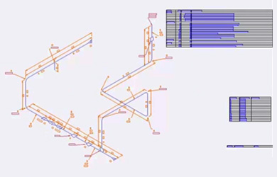
Pipeline Route:
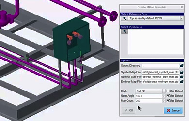
M4 ISO automatically creates unscaled piping isometric drawings directly from Creo Piping models. To ensure the consistent generation of highly legible piping isometrics, M4 ISO utilises a sophisticated algorithm that optimises the layout of the pipeline geometry, labels and dimensions. The orientation of the resulting isometric drawings is controlled by a user-specified North angle.
Automatic Dimensioning
M4 ISO automatically dimensions the piping isometric according to pre-defined options. The piping isometric shows full details of the pipework to be constructed, and all dimensions in terms of length, width and height. For length measurements, the user can optionally request the display of overall dimensions in addition to the dimensions between the individual components. The positioning of dimensions in relation to the pipe geometry can also be precisely controlled.
Height Measurements
M4 ISO piping isometrics also include height data. The user can specify whether height data is to be shown only at end points, or also displayed at pipe bends.
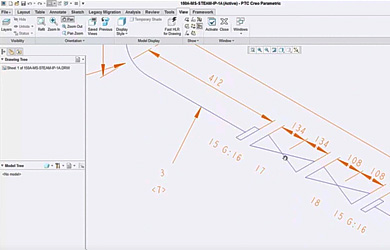
Angles and Falls
When M4 ISO encounters pipework that is not aligned with the isometric drawing’s coordinate system it handles this automatically. Pipe falls and small angles are handled by dimensioning end-points and applying a directional slope symbol. Larger angles are annotated with coordinate dimensions and single or compound cross-hatching, making it very clear to the fabricator the way in which the pipe centreline is offset.
Extensible Symbol Library
M4 ISO is supplied with a comprehensive library of symbols, which are used to represent piping components on the piping isometric drawings. If required, the symbol catalogue can be extended to include company-specific symbols.
Welds
M4 ISO automatically calculates and displays the position of pipe welds, based on the Creo Piping model data. Weld lists can also be generated with blank spaces ready to accept Welder, Inspection and Testing signatures.
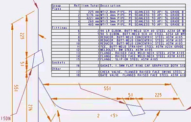
Bills of Materials
M4 ISO automatically generates a configurable bill of materials (BOM) from the Creo Piping model data. BOMs can be placed directly onto the isometric drawing and output to CSV format, ready for use with downstream systems (e.g. Excel).
Pipe Spools
M4 ISO also generates a list of pipe spools: sections of fully welded pipework delivered which are delivered as a single piece. The system automatically recognises spool boundaries where components are not welded together, e.g. flanged connections or valves.
Pipe Cut-Lengths
M4 ISO generates detailed cut-length lists, which are lists of individual cut pieces of pipe with end preparations, required for fabrication by the manufacturer. For on-site adjustments the Creo pipes to be produced can be extended by a certain length.
Using Diagram Styles
Users choose from a variety of different styles prior to automatically generating their isometrics. Each style defines a different level of detail, including the amount of information displayed for fabrication, quantity of dimensions or size of drawing.
Templates
M4 ISO provides blank templates onto which the piping isometrics are generated.
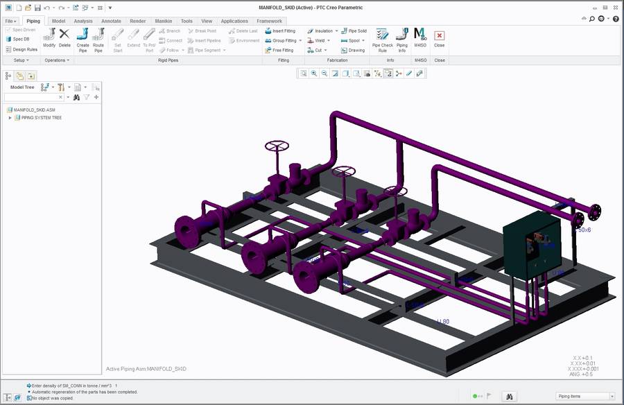
3D view
The drawing template for the pipeline isometrics can be extended by a Creo 3D view of the corresponding pipeline. This is then updated with every update of the isometry.
Configurable Diagram Styles
M4 ISO allows administrators to configure their own isometric drawing styles according to company or project-specific requirements. Line styles, fonts, colours and the layers to be used are all configurable. The format and drawing location of the bill of materials, pipe cut-length, spool and weld lists, can all be configured. Additionally, the content of the bill of materials list can be grouped by component class. A high-degree of control is provided for dimensioning, together with options for cross-hatching out-of-plane pipe slopes. A wide range of labelling options is also provided for connections and termination points.