What's New in version 4.3 of M4 ISO for Creo
M4 ISO Isometrics for PTC Creo® Piping is a software programme that has been developed specially for pipeline construction, it facilitates the automatic creation of unscaled Piping Isometrics drawings from 3D pipeline model data. The new, improved, version 4.1 of M4 ISO Isometrics for PTC Creo Piping is now available.
Support for Creo 11
As of version 4.3, M4 ISO Isometrics for PTC Creo® Piping supports Creo version 11. This enables you to benefit from the latest Creo 11 and M4 ISO 4.1 functionality.
User Notes for components ensures better communication
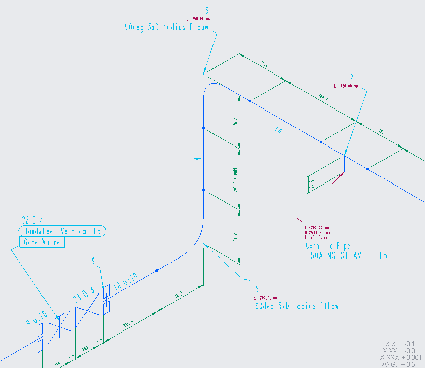
From version 4.1, multiple notes can be added to individual piping components via the M4 ISO dialog in PTC Creo Piping. The style of individual notes can be selected from up to ten different templates defined in the standard system. This enables the display of further manufacturing and erection information on the piping isometric drawing in addition to the data available from the 3D design, thereby improving the communication between designer and manufacturer.

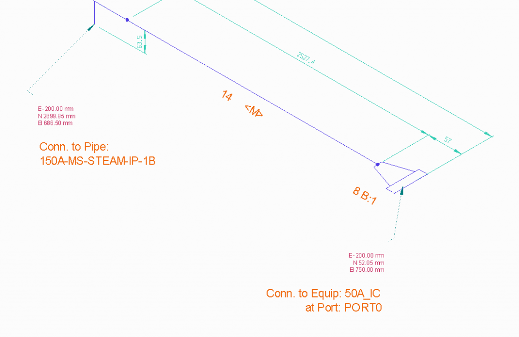
“Connected To” texts for easy cross-referencing of isometrics

Support for feet and fractional inch units of measurement
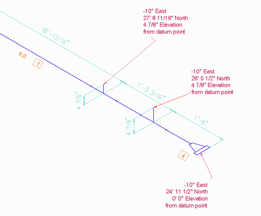
Previously, M4 ISO for PTC Creo Piping supported decimal-metric and decimal-inch units of measurement. As of version 4.1, the software also supports fractional inches (e.g. 20 ¼”) and fractional feet & inches (e.g. 4’ 20 ¼”). These new options allow companies to produce isometric drawings with imperial units that are appropriate for their projects and fabrication processes, especially when operating internationally.

Table layout enhancements
The layout of tables on piping isometric drawings has been significantly enhanced in M4 ISO version 4.1. The widths of table columns, and the texts they contain, can now be configured to suit your requirements. You can specify that the width of a column automatically adjusts to the widest text within the column, or that text automatically wraps to fit in a column of a specified width. These settings greatly increase the readability and positioning of tables as well as ensuring conformity to company standards.
Sorting by Column Values
From version 4.1 of M4 ISO, the Bill of Materials table can be sorted dependant on the values of a pre-defined column. The user can configure both the grouping of the components and their sort order within each group. This means that the sorting of the tables can now be better configured to suit company or project requirements.

Support for property change breaks
From version 4.1, property change breaks can be inserted into a pipe design in PTC Creo to represent property changes such as supplier, or specification, or the extent of insulation. Each break has a direction and a text note associated with each side of the break. The breaks are automatically displayed on the corresponding isometric drawings generated by M4 ISO. Each break is represented as a symbol together with the associated text note. Property change breaks provide a clear demarcation of responsibilities and specifications, thus avoiding misunderstandings during fabrication and assembly.
Display of Flow direction
From version 4.1, flow direction components can be inserted into a pipe in Creo. This results in a corresponding flow direction symbol being automatically displayed on the pipe in the isometric drawing generated by M4 ISO. The display of flow direction is very useful for pipework fabrication and assembly, and subsequently for maintenance purposes.
Configurable user note spacing
User-defined display on multiple pages
To make a complex piping isometric drawing readable, it can sometimes be beneficial to display it on multiple pages. M4 ISO has always allowed the user to specify the maximum number of pipe parts that can appear on a page, which determines how a piping isometric is automatically split for representation on multiple pages. However, with version 3.0, M4 ISO also offers the user the possibility to define individual split points on the pipe to give much greater control over the splitting process. Users can now define precisely when and where a piping isometric is split.
Enhanced cutting allowances
User-defined cutting allowances were added at version 2.0 which enabled the user to specify additional lengths of tube to accommodate on-site bending and fabrication processes. In version 3.0 we have further improved this functionality. It is now possible show where cutting allowances have been assigned to pipes, which makes it easier to edit and remove them.
Reuse of drawings
With version 3.0, M4 ISO now reuses the previous version of a piping isometric drawing as the basis for the next version. The advantage of this is that any Creo entities (e.g. notes and 3D views etc.) that were manually added by the user to the previous version, are retained on the new version. Only the M4 ISO generated data (e.g. isometric views and tables etc.) are updated on the new version.
Optimized placement of labels
With the new M4 ISO version 3.0, significant enhancements have been made to the fundamental algorithms that control the placement of individual notes and labels. This means that even with very complex and dense isometrics, the notes and labels are optimally positioned.
Management of temporary files
With version 3.0, M4 ISO offers additional options that make it easier to manage temporary files created during the isometric generation process. The automatic deletion of these files can be enabled to reduce the amount of data generated.
Bending tables enhanced
With version 2.5, bend tables are enhanced with further configuration options. Cutting allowances, nominal lengths, and adjusted lengths can now all be displayed in bend tables. This enables pipe designs to be better described for transfer to bending machines, ready for manufacture.
Display of Cutting allowances
With the new version of M4ISO, cutting allowances that have been assigned to pipes in Creo, can now be automatically displayed in the corresponding dimensions on the piping isometric drawing.
Display of Cut Start Labels
M4 ISO now offers the possibility to automatically display a label on the piping isometric drawing at the start of each cut pipe length. The label indicates the start of the pipe in relation to the corresponding bending instructions for the pipe.
Generation of ISOX files Only
The new version of M4 ISO enables users to specify that only M4 ISO’s native ISOX files are to be generated. A new ISOX File(s) Only checkbox has been added to the M4 ISO dialog which, when checked, causes the Piping Isometric drawing generation step to be skipped, so that only the ISOX files are generated.
Additional configuration options
From version 2.5, M4 ISO offers additional configuration options to enable the software to be further configured to suit individual customer requirements.
Enhanced dimensioning of non-orthogonal pipe segments
In version 2.4, the dimensioning of non-orthogonal pipe segments has been enhanced, and an additional option to dimension them with a rectangular box has also been added. This makes it easier for the user to determine the size and shape of non-orthogonal pipe segments, which leads to reduced errors during fabrication of the pipework.
Improved pipeline selection
In version 2.4, the selection of individual pipelines and spools has been improved, making it possible to generate the associated piping isometrics even faster.
New bend table functionality
Version 2.4 introduces bend table functionality. A table of pipe bends can now be automatically generated and placed on the drawing, and also output to a CSV file if required. This is particularly beneficial where pipe bening machines are used for pipework fabrication.
Extended configuration
In version 2.4, the options for configuring the software have been extended, which enables M4 ISO to be better adapted to meet specific customer requirements.
Support for Creo 4.0
As of version 2.3, M4 ISO Isometrics for PTC Creo® Piping supports Creo version 4.0. This enables you to benefit from the latest Creo 4.0 and M4 ISO 2.3 functionality.
Cutting allowances for pipelines
As of version 2.3, cutting allowances can be applied to pipelines. Cutting allowances are typically needed for on-site fitting and welding work, and for pipe bending. Both positive and negative allowances are supported. The allowances affect the corresponding sizes that appear in parts lists, cutting lists and bend tables, but they do not affect the pipeline dimensions shown on the isometric drawing, which are the actual dimensions derived from the pipeline model.
Support for Spool Isometrics
As of Version 2.3, M4 ISO recognises pre-defined Creo pipe spools within the Creo pipe assembly and displays each pipe spool on a Spool Isometric drawing. As a result, the fabrication of individual pipe spools can be more easily separated from the overall pipeline assembly process.
Enhanced naming conventions
As of version 2.3, piping isometric drawings generated by M4 ISO can be named using either the Creo assembly name or the Creo pipe name. The assembly name is typically preferred by Windchill PDMLink users because it aids the association of the generated drawings with the model files in Windchill PDMLink.
Support for Creo parameters
As of version 2.3, M4 ISO provides the capability to use Creo parameter values in M4 ISO parts list tables. This means that Creo users who do not use specification-driven piping can now use Creo parameters to directly specify material descriptions and part numbers.
Support for bend tables
With version 2.3, M4 ISO provides support for bend tables, which are typically used for quality control and to provide input for bending machines. The bend table displays the position of each pipe bend relative to one end of the pipe, together with the radius of each bend. The bend table data can also be automatically exported to a CSV file to facilitate data transfer to pipe bending machines.
Customer-oriented enhancements
The new version of M4 ISO also includes enhancements arising directly from customer feedback and requests. For example, improved support for imperial (English) units of measurement was implemented. The extent of cross-hatching applied to pipe elevation and fall angles can now be specified, so as to enhance the overall clarity of the isometric drawing.
Generating drawing templates now easier
In Version 2.2, drawing templates for pipeline isometric drawings can be generated in Creo itself. These templates can then be configured and modified in accordance with the company standard.
Adding a 3D view
From Version 2.2, a 3D view of the pipeline system can also be added to the pipeline isometrics. This is updated with each isometric update. The 3D view provides an even better overview when producing the pipeline.
Generating many drawings simultaneously
Version 2.2 of M4 ISO can generate even more pipeline isometrics simultaneously. As a result, M4 ISO speeds up the isometric production process even further, allowing an even higher degree of automation.
Support for non-specification-driven pipeline design in Creo
In Creo, pipeline design is possible either with pipeline specifications or entirely without them. With the new version, M4 ISO now also supports non-specification-driven pipeline design.
Displaying unknown components
Starting from the new version, M4 ISO uses a standard symbol for each unknown component which is not assigned in the configuration. The parts list then contains the relevant information on the symbol. As a result, isometrics can be generated and the pipelines produced even if the configuration is incomplete.
