P&ID Software Features
Contact our consultants: by phone +49 2841 91840 or by E-Mail
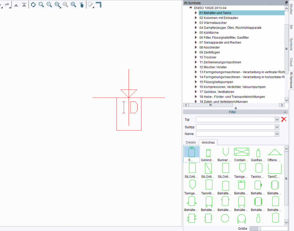
The software contains extensive P&ID catalogues in accordance with the EN ISO, ANSI and ISA standards. The individual symbol catalogues can also be adapted and supplemented with new symbols, enabling companies to create or import individual symbol catalogues that meet company-specific requirements. Complete groups, consisting of equipment, lines and instrumentation, can also be stored as group symbols in the symbol catalogue.
Users can customise P&ID symbols, create new symbols, extend the catalogs, and create new symbol catalogs. Users can configure catalogs for specific projects or customers, and save these configurations for easy retrieval.
Intelligent P&ID Symbols and Lines
The symbols and process and instrumentation lines contained in M4 P&ID diagrams include important process information for downstream use, stored in attributes. Some equipment symbols also include intelligent connection points for connecting pipes, for example.
Intelligent symbol numbering*
The numbering of P&ID symbols in M4 P&ID can be customised to meet respective company requirements, ensuring that all existing numbering systems can be realised for individual components. Intelligent numbering can also be defined only for specific components or equipment types. Multiple labelling configurations can also be managed if they are required for different projects or customers.
Configurable Attributes
Symbol and line attributes can be edited or augmented in line with company requirements. Companies can decide whether attributes are to be freely definable or restricted to certain values.
Dynamic P&ID Creation & Editing
M4 P&ID contains dynamic tools for placing and moving symbols and groups of symbols. A configurable grid is available to aid in the accurate placement on the schematic.
Automatically Maintained Connections
Equipment placed on pipes, such as valves or controls, is automatically aligned. As users move symbols or groups of symbols, M4 P&ID automatically maintains connections, moving an entire piping system to the new position, for example.
Complete Piping Systems Design
In M4 P&ID, users can route process lines between connection points on their P&ID symbols to quickly create piping systems. Pipes are automatically aligned vertically and horizontally.
Configurable Schematics
Extensive Instrumentation Catalogs
M4 P&ID users have access to extensive catalogs of instrumentation lines and symbols, and can dynamically place and route components. Symbol texts can be edited at any time.
Real-Time Reporting
Users can generate configurable reports and parts lists at any time during the design process, displaying all the background information contained in the schematic.
Tools for Providing P&ID Details
M4 P&ID contains dynamic tools for adding details like line cross overs and flow direction arrows. Users can add pipe branch, symbol and line bore texts, as well as vendor, responsibility and pipe specification break symbols.
Configurable P&ID Attributes
Users can add or edit process line or symbol attributes at any time during the design process.
Photos and scans in drawings*
The R&I flow diagrams can also be supplemented with colour or monochrome photos or scans. This means that existing plans, photos, scans or other image documents can also be incorporated into the flow diagrams. Because they are saved inside the drawing this ensures easy access for the entire team. The individual graphics or photos can also be edited and adapted to the requirements of the individual drawing.
On and Off-Sheet Connections
Large P&IDs are often divided into sheet areas, or across multiple sheets. M4 P&ID users intelligently link these areas by adding on- and off-sheet connectors, which are graphically displayed on the schematic.
Multi-Sheet Reporting and QA
The information about these connection is also stored in the background, allowing users to generate reports and check P&ID consistency across multiple sheets.
Project-Based P&ID Working Sets
M4 P&ID users can collect several drawings with the P&IDs they contain in working sets, which then contain all the process information about a particular project.
Project-wide Reports and Parts Lists
Users can then run P&ID consistency checks across a working set and report on any issues found. Users can generate parts lists, line lists and from/to lists from entire working sets, or from individual drawings within the set.
P&ID Consistency Checks
Users can quality check their intelligent schematics at any time during the design process. The software checks for correct pipe connections; whether all equipment connection points have been used; whether process lines have been fully labelled; and whether there are any open pipes.
Issue Reports and Error Highlighting in P&IDs
P&ID Parts Lists, Line and From/To Lists
P&ID Data Export for Downstream Use
Users can preview, print, or place lists as tables on their P&IDs. P&ID data can also be exported to CSV for downstream use in Micrsoft Excel® for example.
P&ID Groups Saved as Symbols
In order speed up and part-automate P&ID creation for process engineers regularly creating similar schematics, M4 P&ID allows users to save parts of P&IDs as a special P&ID symbol. The special catalog provided also allows users to create different categories for their symbols groups.
Individual Attribute Retention
M4 P&ID can retain the attributes on individual symbols in a saved P&ID group. Users can edit these attributes as required after the group has been placed.
Project-Specific P&ID System Configurations
M4 P&ID allows users to save and load different system configurations, enabling designers to adapt their P&IDs to specific project or customer requirements.
Customer-Specific P&IDs
Complementary 2D Drafting Functionality
M4 P&ID provides an extensive set of 2D tools in support of P&ID creation. These tools make it quick and easy to create & edit P&ID symbols.
Ability to Add 2D Drawings and Details
Configurable DXF/DWG Interface
M4 P&ID provides an accurate DXF/DWG interface for easy data exchange and communication with customers and suppliers. It allows imported DXF/DWG data to be used as geometry on a P&ID, as well as P&IDs to be exported to DXF/DWG.
Project-Specific Export and Import Configurations
Users can configure the DXF/DWG interface for project or client-specific requirements. M4 P&ID supports all current versions of the DWG/DXF format.
Advanced configuration & administration*
M4 P&ID already provides extensive configuration capabilities in the FX package. In the Premium version, the software offers even more flexibility when installing the software in a multi-user environment or for central administration of catalogues. Get in touch with us and let us advise you on the possibilities.
* Only included in the M4 P&ID Premium package
